-1-
保证和声明 版权 ©2018 苏州普源精电科技有限公司 商标信息 RIGOL 是苏州普源精电科技有限公司的注册商标。 文档编号 QGB11000-1110 声明 本公司产品受中国及其它国家和地区的专利(包括已取得的和正在申请的专利)保护。 本公司保留改变规格及价格的权利。 本手册提供的信息取代以往出版的所有资料。 本手册提供的信息如有变更,恕不另行通知。 对于本手册可能包含的错误,或因手册所提供的信息及演绎的功能以及因使用本手册而导致的 任何偶然或继发的损失,RIGOL 概不负责。 未经 RIGOL 事先书面许可,不得影印、复制或改编本手册的任何部分。 产品认证 RIGOL 认 证 本 产 品 符 合 中 国 国 家 产 品 标 准 和 行 业 产 品 标 准 及 ISO9001:2015 标 准 和 ISO14001:2015 标准,并进一步认证本产品符合其它国际标准组织成员的相关标准。 联系我们 如您在使用此产品或本手册的过程中有任何问题或需求,可与 RIGOL 联系: 电子邮箱:service@rigol.com 网址:www.rigol.com 一般安全概要 1. 2. 3.
产品上的安全术语: DANGER WARNING CAUTION 表示您如果不进行此操作,可能会立即对您造成危害。 表示您如果不进行此操作,可能会对您造成潜在的危害。 表示您如果不进行此操作,可能会对本产品或连接到本产品的其他设备造成 损坏。 产品上的安全符号: 高电压 安全警告 保护性接地端 壳体接地端 测量接地端 保养与清洁 保养 请勿将仪器放置在长时间受到日照的地方。 清洁 请根据使用情况定期对仪器进行清洁。方法如下: 1. 断开电源。 2. 用柔和的清洁剂或清水浸湿软布擦拭仪器外部,请注意不要将水或其他异物通过散热孔进入机 箱内。清洁带有液晶显示屏的仪器时,请注意不要划伤 LCD 显示屏。 注意 请勿使任何腐蚀性的液体沾到仪器上,以免损坏仪器。 警告 重新通电之前,请确认仪器已经干透,避免因水分造成电气短路甚至人身伤害。 文档概述 本文档介绍初次使用DG800系列函数/任意波形发生器时需要了解的信息,包括产品简介、连接电 源、开机检查以及远程控制等。 提示 本手册的最新版本可登陆 RIGOL 网址(www.rigol.com)进行下载。 文档格式的约定 1.
. 操作步骤: 本手册中通常用箭头“”表示下一步操作。例如:Utility系统设置表示按下前面板上的 Utility 功能键后再触摸点击 系统设置菜单标签。 文档内容的约定 DG800系列函数/任意波形发生器包含以下型号。如无特殊说明,本手册以DG832为例介绍其使用 方法。 型号 DG812 DG811 DG822 DG821 DG832 DG831 通道数 2 1 2 1 2 1 最大输出频率 10MHz 10MHz 25MHz 25MHz 35MHz 35MHz 一般性检查 1. 检查运输包装 如运输包装已损坏,请保留被损坏的包装或防震材料,直到货物经过完全检查且仪器通过电性 和机械测试。 因运输造成仪器损坏,由发货方和承运方联系赔偿事宜。RIGOL 公司恕不进行免费维修或更 换。 2. 检查整机 若存在机械损坏或缺失,或者仪器未通过电性和机械测试,请联系您的 RIGOL 经销商。 3.
13 12 11 10 2 3 1 表 1 前面板说明 编号 说明 1 电源键 2 同相位键 3 CH1 输出连接器 4 通道控制区 5 CH2 输出连接器 6 Counter 测量信号输入连接器 7 频率计 1 2 4 5 8 6 7 图 1 前面板 编号 8 9 10 11 12 13 —— 3 表 2 后面板说明 编号 说明 1 10MHz 输入/输出连接器 2 CH1 同步/外调制/触发连接器 3 CH2 同步/外调制/触发连接器 9 4 说明 方向键 旋钮 Menu 键 Home 键 功能键 LCD 触摸显示屏 —— 5 6 图 2 后面板 编号 4 5 6 说明 USB HOST USB DEVICE AC 电源插口 4
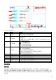
5 4 7 8 9 10 1 表 3 用户界面标识 编号 名称 通 道输出配置 1 状态栏 2 界面切换 3 信息设置 4 状态栏 5 6 7 8 9 10 波形 界面标签 频率 幅度 偏移 相位 2 图 3 用户界面 3 说明 显示各通道当前的输出配置。 左侧圆点置灰,右侧圆点点亮,此时向右滑动屏幕切换至波形 选择界面。 左侧圆点点亮,右侧圆点置灰,此时向左滑动屏幕切换至当前 波形参数设置界面。 :打开 Store 界面。 :打开 Utility 界面。 :执行通道复制功能。 :执行屏幕打印操作。 :表示前面板按键和屏幕被锁定。 :表示关闭蜂鸣器。 :表示仪器处于程控模式。 :表示使用网线成功将仪器连接至局域网。 :表示成功连接 U 盘。 显示各通道当前选择的波形。 显示当前界面的标签。 显示各通道当前波形的频率。 显示各通道当前波形的幅度。 显示各通道当前波形的直流偏移。 显示各通道当前波形的相位。 使用前准备 连接电源 请使用附件提供的电源线将信号发生器连接至 AC 电源中,如下图所示。本信号发生器支持 100-127V,45-440Hz 或 100-240V,45
注意 为避免电击,请确保仪器正确接地。 开机检查 正确连接电源后,按下前面板的电源键 检过程。结束后,屏幕进入默认界面。 打开信号发生器。开机过程中仪器执行初始化过程和自 设置系统语言 DG800 支持多种语言菜单。您可以按 Utility系统设置,然后触摸点击 Language 标签右侧的 参数选择框,选择所需的语言类型。 使用内置帮助系统 DG800 对于前面板上的每个功能按键以及当前显示界面都提供了帮助信息。用户可在操作仪器的 过程中随时查看各项帮助信息。 1. 获取前面板按键帮助 按下 Help/Local 键,然后再按下你所需要获得帮助的前面板按键,仪器界面显示该键的帮 助信息。 2. 获取常用帮助主题 按下前面板 Help/Local 键,弹出如下图所示的界面,触摸点击屏幕中“帮助”,进入帮助列 表界面。此时,您可通过上下滑动屏幕或旋转旋钮滚动列表,然后触摸点击选中相应的帮助项, 仪器界面显示该项的帮助信息。 3.
向导界面提示您进行操作。 4. 帮助的翻页操作 当帮助信息为多页显示时,您可通过手指上下滑动屏幕以滚动帮助信息页面。 5. 关闭当前的帮助信息 当仪器界面显示帮助信息时,用户按下前面板 Help/Local 键,将关闭当前显示的帮助信息。 实例:输出正弦波 本节主要介绍如何从[CH1] 连接器输出一个正弦波(频率为 20kHz,幅度为 2.5Vpp,偏移量为 500mVdc,起始相位为 90°)。 1. 选择输出通道:按下前面板 Output1 键(或通过触摸点击通道输出配置状态栏 2. 3. 4. 5. 6. ) 选中 CH1 通道。此时通道界面以红色显示。 选择正弦波:按下前面板 Menu 键,在弹出的波形选择界面触摸点击 Continuous“Sine” 图标,仪器自动跳转至正弦波参数设置界面。 设置频率:触摸点击频率标签右侧的参数输入框,通过弹出的数字键盘输入 20,选择单位 “kHz”,点击“Ok” 。 设置幅度:触摸点击幅度标签右侧的参数输入框,通过弹出的数字键盘输入 2.
Guaranty and Declaration Copyright © 2018 RIGOL (SUZHOU) TECHNOLOGIES INC. All Rights Reserved. TrademarkInformation RIGOL is a registered trademark of RIGOL (SUZHOU) TECHNOLOGIES INC. PublicationNumber QGB11100-1110 Notices RIGOL products are covered by P.R.C. and foreign patents, issued and pending. RIGOL reserves the right to modify or change parts of or all the specifications and pricing policies at the company’s sole decision.
CAUTION Indicates a potentially hazardous situation or practice which, if not avoided, could result in damage to the product or loss of important data. SafetyTerms on the Product: DANGER WARNING CAUTION It calls attention to an operation, if not correctly performed, could result in injury or hazard immediately. It calls attention to an operation, if not correctly performed, could result in potential injury or hazard.
Format Conventions in this Manual 1. Keys: The keys on the front panel are usually denoted by the format of "Key Name (Bold) + Text Box". For example, Utility. 2. Menu Labels: The menu labels are usually denoted by the format of "Menu Word (Bold) + Character Shading". For example, System Setting. 3. Connectors: The connectors on the front or rear panel are usually denoted by the format of "Connector Name (Bold) + Square Brackets (Bold)". For example, [Counter]. 4.
Product Overview As a multi-functional signal generator, DG800 series function/arbitrary waveform generator integrates many instruments into 1, such as function generator, arbitrary waveform generator, noise generator, pulse generator, harmonic generator, analog/digital modulator, and frequency counter.
Table 2 Rear Panel Description No. Description 1 10MHz In/Out Connector 2 CH1 Sync/Ext Mod/Trig/FSK Connector 3 CH2 Sync/Ext Mod/Trig/FSK Connector 6 No. 4 5 6 Description USB HOST USB DEVICE AC Power Cord Connector 5 4 7 8 9 10 1 2 3 Figure 3 User Interface Table 3 User Interface Icons No.
8 Amplitude 9 Offset 10 Phase Displays the amplitude of the current waveform of each channel. Displays the DC offset of the current waveform of each channel. Displays the phase of the current waveform of each channel. To Prepare for Use To Connect to AC Power Please use the power cord provided in the accessories to connect the signal generator to the AC power source, as shown in the figure below.
then press the desired key for the help information. Then, the corresponding help information is displayed. 2. Obtain the common help topics Press Help/Local on the front panel, and then the following interface is displayed below. Tap "Help" to enter the help interface. At this time, you can tap on the touch screen to move up and down the help items or rotate the knob to scroll up and down the list to select the desired help item. Then, the help information for the item is displayed in the interface. 3.
5. Set offset voltage: Tap the Offset parameter input field to input 500 with the pop-up numeric keypad, and then select "mVdc" as the unit. Tap "Ok". 6. Set start phase: Tap the Phase parameter input field to input 90 with the pop-up numeric keypad, and then select "°" as the unit. Tap "Ok". 7. Enable channel output: Press Output1 or tap the channel output configuration status bar to enable the channel output.