RIGOL Programming Guide DP700 Series Programmable Linear DC Power Supply Jun. 2016 RIGOL TECHNOLOGIES, INC.
RIGOL Guaranty and Declaration Copyright © 2016 RIGOL TECHNOLOGIES, INC. All Rights Reserved. Trademark Information RIGOL is a registered trademark of RIGOL TECHNOLOGIES, INC. Publication Number PGH05101-1110 Software Version 00.01.02 Software upgrade might change or add product features. Please acquire the latest version of the manual from RIGOL website or contact RIGOL to upgrade the software. Notices RIGOL products are covered by P.R.C. and foreign patents, issued and pending.
RIGOL Document Overview This manual is your guide to programming the RIGOL DP700 series programmable linear DC power supply. Main Topics in this Manual: Chapter 1 Programming Overview This chapter introduces how to set up remote communication between the power supply and the PC, the remote control methods, the syntax, symbols, parameters, and abbreviation rules of the SCPI commands. Chapter 2 Command System This chapter introduces the syntax, function, parameters, and usage of each command.
Contents RIGOL Contents Guaranty and Declaration ......................................................................................................... I Document Overview ................................................................................................................. II Chapter 1 Programming Overview......................................................................................1-1 To Build Remote Communication ....................................................................
RIGOL Contents :SOURce Commands ............................................................................................................... 2-22 [:SOURce[]]:CURRent[:LEVel][:IMMediate][:AMPLitude] .............................................. 2-22 [:SOURce[]]:CURRent:PROTection:CLEar ..................................................................... 2-23 [:SOURce[]]:CURRent:PROTection[:LEVel] ...................................................................
Chapter 1 Programming Overview RIGOL Chapter 1 Programming Overview This chapter introduces how to set up remote communication between the power supply and the PC, the remote control methods, the syntax, symbols, parameters, and abbreviation rules of the SCPI commands.
RIGOL Chapter 1 Programming Overview To Build Remote Communication DP700 series power supply can communicate with the PC via the RS232 interface. This section will illustrate how to use the Ultra Sigma software to remotely control the power supply via the RS232 interface. Note: The RS232 protocol command ends with "\n" for the DP700 series. Operation Procedures: 1. Install Ultra Sigma You can download Ultra Sigma from the official website of RIGOL (www.rigol.
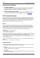
RIGOL Chapter 1 Programming Overview Note: If the test fails, check whether DP700 can communicate with the PC via the RS232 cable normally, whether the current RS232 settings of the software match those of DP700. In the dialog box shown in Figure (b), click "OK". Then the "Add" button in the "RS232 Setting" tab will be enabled. Click "Add", and then the currently selected instrument resource will be displayed on the right section of the window, as shown in Figure (c).
RIGOL Chapter 1 Programming Overview Remote Control Method 1. User-defined programming You can refer to Chapter 2 in this manual to use the SCPI (Standard Commands for Programmable Instruments) commands to control DP700 by programming in LabVIEW, Visual C#, and other development environments. For details, refer to Chapter 4 in this manual. 2. Send SCPI commands via the PC software You can use the PC software to send commands to control DP700 remotely. RIGOL Ultra Sigma is recommended.
Chapter 1 Programming Overview RIGOL 3. Square Brackets [ ] The contents (keywords or parameters) in the square brackets can be omitted. If the parameter is omitted, it will be set to the default. For example, when sending the :MEASure[:VOLTage][:DC]? command, you can select any one of the following four commands, as they can achieve the same effects as the :MEASure[:VOLTage][:DC]? command. :MEASure? :MEASure:DC? :MEASure:VOLTage? :MEASure:VOLTage:DC? 4.
RIGOL Chapter 2 Command System Chapter 2 Command System This chapter introduces the syntax, functions, parameters, and usage of each command. Contents in this chapter: :APPLy Command :DISPlay Command IEEE488.
RIGOL Chapter 2 Command System :APPLy Command The :APPLy command provides the most straightforward method to program the power supply over the remote interface. You can set the output voltage and current in one command. As long as their setting values are within the settable range, after you execute the command, the output voltage and current will make changes accordingly.
RIGOL Chapter 2 Command System :DISPlay Command The :DISPlay command is used to turn on or off the display. :DISPlay[:WINDow][:STATe] Syntax :DISPlay[:WINDow][:STATe] :DISPlay[:WINDow][:STATe]? Description Turns on or off the display. Queries the on/off state of the display. Parameter Name Type Bool Range {ON|OFF} Default ON Remarks Only when DP700 is in remote mode, can the :DISPlay:WINDow:STATe OFF command be valid.
RIGOL Chapter 2 Command System IEEE488.2 Common Commands Command List: *IDN? *OPT? *RCL *RST *SAV *TST? *IDN? Syntax *IDN? Description Queries the identification string. Return Format RIGOL TECHNOLOGIES,,, Wherein, : indicates the model number of the instrument. : indicates the serial number of the instrument. : indicates the software version of the instrument.
RIGOL Chapter 2 Command System *RCL Syntax *RCL Description Recalls the state file or timer file stored in the specified location in the internal non-volatile memory of the power supply. Parameter Name Type Discrete Range {1|2|3|4|5|6|7|8|9|10|11|12} Default -- Remarks The internal non-volatile memory of DP700 series power supply provides ten storage locations for state files and two for timer files.
RIGOL Parameter Name Chapter 2 Command System Type Discrete Range {1|2|3|4|5|6|7|8|9|10|11|12} Default -- Remarks The internal non-volatile memory of DP700 series power supply provides ten storage locations for state files and two for timer files. They are used to store the state information of the instrument and the timer parameters, respectively. : {1|2|3|4|5|6|7|8|9|10}: indicates the storage location for the state file, which corresponds to "State1...
RIGOL Chapter 2 Command System :INSTrument Commands Command List: :INSTrument:NSELect :INSTrument[:SELEct] :INSTrument[:SELect] :INSTrument:NSELect Syntax :INSTrument:NSELect :INSTrument:NSELect? Description Selects the current channel. Queries the currently selected channel.
RIGOL Chapter 2 Command System :LIC Command The :LIC command is used to install the options. DP700 series provides the following options: Trigger, Timer, and High Resolution. If you need any options, please purchase them and install them properly. Trigger: provides the trigger input and output function; the order No. is TRIGGER-DP700. Timer: outputs based on the preset voltage and current values; the order No. is TIMER-DP700. High Resolution: improves the resolution of the instrument; the order No.
RIGOL Chapter 2 Command System :MEASure Commands Command List: :MEASure:ALL[:DC]? :MEASure:CURRent[:DC]? :MEASure:POWEr[:DC]? :MEASure[:VOLTage][:DC]? :MEASure:ALL[:DC]? :MEASure:CURRent[:DC]? :MEASure:POWEr[:DC]? :MEASure[:VOLTage][:DC]? Syntax :MEASure:ALL[:DC]? [] :MEASure:CURRent[:DC]? [] :MEASure:POWEr[:DC]? [] :MEASure[:VOLTage][:DC]? [] Description Queries the voltage, current, and power value measured on the channel output terminal.
RIGOL Chapter 2 Command System :MEMory Commands The :MEMory commands are used to save the state of the instrument or the timer parameters to the specified location of the internal memory, delete, read, lock, and unlock the saved file in the internal memory.
RIGOL Chapter 2 Command System :MEMory[:STATe]:LOAD Syntax :MEMory[:STATe]:LOAD , Description Reads the state files (RSF) or timer files (RTF) stored in the specified locations of the internal non-volatile memory. Parameter Name Type Discrete Discrete Range {RSF|RTF} When is RSF, the range of is {1|2|3|4|5|6|7|8|9|10}. When is RTF, the range of is {1|2}.
RIGOL Chapter 2 Command System Remarks The internal non-volatile memory of DP700 series power supply provides ten storage locations for state files and two for timer files. They are used to store the state information of the instrument and the timer parameters, respectively. Storage location of the state file (RSF) The range of is {1|2|3|4|5|6|7|8|9|10}, which corresponds to "State1...State10" in the storage and recall interface of the instrument.
RIGOL Chapter 2 Command System You can also send the *SAV command to save the current state or timer parameters of the power supply to the internal nonvolatile memory.
RIGOL Chapter 2 Command System :OUTPut Commands The :OUTPut commands are used to enable or disable the channel output, query the channel output mode, set and query the overvoltage/overcurrent protection information.
RIGOL Chapter 2 Command System Example :OUTPut:CVCC? CH1 :OUTPut:MODE? /*Queries the channel output mode*/ Return Format CV, CC, or UR :OUTPut:OCP:ALAR? :OUTPut:OCP:QUES? Syntax :OUTPut:OCP:ALAR? [] :OUTPut:OCP:QUES? [] Description Queries whether the overcurrent protection (OCP) has occurred.
RIGOL Chapter 2 Command System :OUTPut:OCP:CLEAR Syntax :OUTPut:OCP:CLEAR [] Description Clears the internal OCP flag and the OCP prompt message. Parameter Name Type Discrete Range DP711: {CH1|P30V} DP712: {CH1|P50V} Default CH1 Remarks Before executing the command, ensure that you have located and resolved the problem for causing the overcurrent protection.
RIGOL Chapter 2 Command System overcurrent protection function. You can send the :OUTPut:OCP:VALue or [:SOURce[]]:CURRent:PROTection[:LEVel] command to set the channel overcurrent protection value.
RIGOL Chapter 2 Command System Return Format A real number Related Commands :OUTPut:OVP[:STATe] [:SOURce[]]:CURRent:PROTection:STATe [:SOURce[]]:CURRent:PROTection[:LEVel] :OUTPut:OVP:ALAR? :OUTPut:OVP:QUES? Syntax :OUTPut:OVP:ALAR? [] :OUTPut:OVP:QUES? [] Description Queries whether the overvoltage protection (OVP) has occurred.
RIGOL Chapter 2 Command System :OUTPut:OVP:CLEAR Syntax :OUTPut:OVP:CLEAR [] Description Clears the internal OVP flag and the OVP prompt message. Parameter Name Type Discrete Range DP711: {CH1|P30V} DP712: {CH1|P50V} Default CH1 Remarks Before executing the command, ensure that you have located and resolved the problem for causing the overvoltage protection.
RIGOL Chapter 2 Command System You can send the :OUTPut:OVP:VALue or [:SOURce[]]:VOLTage:PROTection[:LEVel] command to set the channel overvoltage protection value.
RIGOL Chapter 2 Command System Return Format A real number Related Commands :OUTPut:OVP[:STATe] [:SOURce[]]:VOLTage:PROTection:STATe [:SOURce[]]:VOLTage:PROTection[:LEVel] :OUTPut[:STATe] Syntax :OUTPut[:STATe] [,] :OUTPut[:STATe]? [] Description Enable or disable the channel output. Queries the on/off state of the channel output.
RIGOL Chapter 2 Command System :SOURce Commands The :SOURce commands are used to set and query the channel output voltage/current, and the overvoltage/overcurrent protection information. These commands can be used to modify a single parameter, with a great flexibility.
RIGOL Chapter 2 Command System [:SOURce[]]:CURRent:PROTection:CLEar Syntax [:SOURce[]]:CURRent:PROTection:CLEar Description Clears the internal OCP flag and the OCP prompt message. Parameter Name Type Discrete Range {1} Default 1 Remarks Before executing the command, ensure that you have located and resolved the problem for causing the overcurrent protection.
RIGOL Chapter 2 Command System For the query command, MINimum indicates querying the minimum settable value of the channel overcurrent protection; MAXimum indicates querying the maximum settable value of the channel overcurrent protection. You can also send the :OUTPut:OCP:VALue command to set the channel overcurrent protection value.
RIGOL Chapter 2 Command System [:SOURce[]]:CURRent:PROTection:TRIPped? Syntax [:SOURce[]]:CURRent:PROTection:TRIPped? Description Queries whether the overcurrent protection (OCP) has occurred.
RIGOL Example :VOLTage 20 :VOLTage? Chapter 2 Command System /*Sets the channel output voltage to 20 V*/ /*Queries the channel voltage setting value*/ Return Format A real number Related Command :APPLy [:SOURce[]]:VOLTage:PROTection:CLEar Syntax [:SOURce[]]:VOLTage:PROTection:CLEar Description Clears the internal OVP flag and the OVP prompt message.
RIGOL Chapter 2 Command System Parameter Name Type Discrete Real Range DP711: {CH1|P30V} DP712: {CH1|P50V} Standard: 0.01 V to 33 V High resolution option (ordering number: HIRES-DP700) installed: 0.
RIGOL Chapter 2 Command System You can send the :OUTPut:OVP:VALue or [:SOURce[]]:VOLTage:PROTection[:LEVel] command to set the channel overvoltage protection value.
Chapter 2 Command System RIGOL :SYSTem Commands Command List: :SYSTem:BEEPer:IMMediate :SYSTem:BEEPer[:STATe] :SYSTem:BRIGhtness :SYSTem:COMMunicate:RS232:BAUD :SYSTem:COMMunicate:RS232:DATABit :SYSTem:COMMunicate:RS232:PARItybit :SYSTem:COMMunicate:RS232:STOPBit :SYSTem:ERRor? :SYSTem:FAN? :SYSTem:KLOCk :SYSTem:KLOCk:STATe :SYSTem:LANGuage:TYPE :SYSTem:LOCal :SYSTem:LOCK :SYSTem:POWEron :SYSTem:PRINT? :SYSTem:REMote :SYSTem:RWLock[:ST
RIGOL Chapter 2 Command System :SYSTem:BEEPer[:STATe] Syntax :SYSTem:BEEPer[:STATe] :SYSTem:BEEPer[:STATe]? Description Turns on/off the beeper. Queries the on/off state of the beeper. Parameter Name Type Bool Range {ON|OFF} Default ON Remarks When the beeper is turned on, the beeper sounds when you perform the following operations.
RIGOL Chapter 2 Command System :SYSTem:COMMunicate:RS232:BAUD Syntax :SYSTem:COMMunicate:RS232:BAUD :SYSTem:COMMunicate:RS232:BAUD? Description Sets the baud rate of the RS232 interface. Queries the baud rate of the RS232 interface. Parameter Name Type Discrete Range {7200|9600|14400|19200|38400|57600|115200} Default 9600 Remarks Communication can be set up between the DP700 series power supply and the PC via the RS232 interface.
RIGOL Chapter 2 Command System :SYSTem:COMMunicate:RS232:PARItybit Syntax :SYSTem:COMMunicate:RS232:PARItybit :SYSTem:COMMunicate:RS232:PARItybit? Description Sets the parity of the RS232 interface. Queries the parity of the RS232 interface. Parameter Name Type Discrete Range {NONE|ODD|EVEN} Default NONE Remarks Communication can be set up between the DP700 series power supply and the PC via the RS232 interface.
RIGOL Chapter 2 Command System :SYSTem:ERRor? Syntax :SYSTem:ERRor? Description Queries the last error message in the error queue and clears the error message. Remarks DP700 series allows you to view the last 5 errors. Return Format The number and contents of the error message, such as -113,"Undefined header; keyword cannot be found" :SYSTem:FAN? Syntax :SYSTem:FAN? Description Queries the self-test result of the fan. Remarks The power supply performs the self-test operation when it is powered on.
RIGOL Chapter 2 Command System The keys locked cannot be used. You are allowed to lock the specified keys or all keys on the front panel (including the knob, but excluding ).
RIGOL Chapter 2 Command System Related Commands :SYSTem:RWLock[:STATe] :SYSTem:LOCal :SYSTem:LANGuage:TYPE Syntax :SYSTem:LANGuage:TYPE :SYSTem:LANGuage:TYPE? Description Selects the system language. Queries the currently selected language. Parameter Name Type Discrete Range {EN|CH} Default -- Remarks DP700 series power supply provides the help information, prompt message, and interface display in both Chinese and English version.
RIGOL Chapter 2 Command System :SYSTem:LOCK Syntax :SYSTem:LOCK :SYSTem:LOCK? Description Locks or unlocks the front panel. Queries whether the front panel is locked or not. Parameter Name Type Bool Range {ON|OFF|1|0} Default OFF Remarks DP700 series power supply provides the key locking functions to avoid any loss caused by misoperation. When the front panel is locked, it indicates that all keys (except On/Off, on the front panel are locked. The icons interface.
RIGOL Chapter 2 Command System :SYSTem:PRINT? Syntax :SYSTem:PRINT? Description Reads the data stream of the image currently displayed on the screen (screen shot). Return Format A string :SYSTem:REMote Syntax :SYSTem:REMote Description Enables the power supply to shift from the local mode to the remote mode. Remarks When the power supply returns to the remote mode, all keys (except On/Off, on the front panel are locked.
RIGOL Chapter 2 Command System :SYSTem:SAVer Syntax :SYSTem:SAVer :SYSTem:SAVer? Description Enables or disables the screen saver function. Queries the on/off state of the screen saver function. Parameter Name Type Bool Range {ON|OFF} Default OFF Remarks When the screen saver function is enabled, if no operation is performed on the front panel for more than 25 minutes, the instrument automatically enters the screen saver mode; if it persists for another 12.
RIGOL Chapter 2 Command System Parameter Name Type Bool Range {ON|OFF} Default OFF Remarks Trigger input indicates that the external trigger input signal controls the on/off state of the channel output. Pin 8 of the RS232 interface on the rear panel is used to receive the external trigger input signal. When it receives a high level signal (≥ 2.1 V, 10 mA), the channel output will be turned on; when it receives a low level signal (≤0.7 V, 10 mA), the channel output will be turned off.
RIGOL Chapter 2 Command System :SYSTem:VERSion? Syntax :SYSTem:VERSion? Description Queries the SCPI version of the system. Return Format YYYY.V, for example, 1999.0 Wherein, YYYY: indicates the version year. V: indicates the number of edition times in the version year.
RIGOL Chapter 2 Command System :TIMEr Commands Command List: :TIMEr:CYCLEs :TIMEr:ENDState :TIMEr:GROUPs :TIMEr:PARAmeter :TIMEr[:STATe] :TIMEr:TRIGger :TIMEr:CYCLEs Syntax :TIMEr:CYCLEs :TIMEr:CYCLEs? Description Sets the number of cycles for the timer. Queries the number of cycles selected for the timer.
RIGOL Chapter 2 Command System :TIMEr:ENDState Syntax :TIMEr:ENDState :TIMEr:ENDState? Description Sets the end state of the timer. Queries the end state selected for the timer. Parameter Name Type Discrete Range {OFF|LAST} Default OFF Remarks "End State" refers to the state of the instrument after it has completed outputting groups of voltage and current values for a specified number of times (the total number of output groups) when "cycles" is N[,] (a finite value).
RIGOL Chapter 2 Command System of output groups), the timing output will be terminated. At this time, the state of the instrument is determined by the return value that you have set. When "cycles" is set to I (Infinite), "End State" is invalid.
RIGOL Chapter 2 Command System The data block header describes the data length, beginning with a symbol #. For example, in the above string, #9000000036 indicates the data block header. The 9 figures following the symbol # indicate the 9-digit data (000000036), which describes the length of the data stream (36 bytes). Each group of the timing parameters is in the format of "group ID,output voltage,output current,duration time". Each group of parameters is separated by a semi-colon.
RIGOL Chapter 2 Command System DEFault: when the timing output is enabled, the instrument automatically outputs based on the parameter configuration of the timer. SINGle: when the timing output is enabled, one single press on the OK enables a single output based on a group of timing parameters, until the instrument has completed outputting operation for a specified number of times (total number of output groups).
Chapter 3 Application Instances RIGOL Chapter 3 Application Instances This chapter provides the application instances of the SCPI commands. The main functions of the power supply can be realized through a series of SCPI commands. Note: 1. The instances in this chapter take DP711 as an example. The range of certain parameters for other models may be different. Therefore, you need to adjust the parameter range for the model that you use if necessary. 2.
RIGOL Chapter 3 Application Instances Constant Voltage Output Requirement Functions to be realized: constant voltage output, the output voltage is 30 V, the output current is 2 A, the overcurrent protection function is enabled and the overcurrent protection value is 2 A.
Chapter 4 Programming Examples RIGOL Chapter 4 Programming Examples This chapter lists some examples by programming based on NI-VISA in the LabVIEW and Visual C# to remotely control the power supply. NI-VISA (National Instrument-Virtual Instrument Software Architecture), developed by NI (National Instrument), provides an advanced programming interface to communicate with various instruments through their bus lines.
RIGOL Chapter 4 Programming Examples LabVIEW Programming Example Program used in this instance: LabVIEW 2010 Function realized in this instance: search for the instrument address, connect to the instrument, send commands and read return values. 1. Run LabVIEW 2010, and then create a VI file named DP700_Demo_Labview. 2. Add the following controls to the interface of the front panel.
Chapter 4 Programming Examples 3. Click Show Block Diagram under the Window menu to create an event structure. 4. Add an event, including Connect, Writing, Read, and Exit.
RIGOL Chapter 4 Programming Examples (2) Write (including error confirmation): 4-4 DP700 Programming Guide
Chapter 4 Programming Examples RIGOL (3) Read (including error correction advice): DP700 Programming Guide 4-5
RIGOL Chapter 4 Programming Examples (4) Exit: 5. 4-6 Run the program, and set the parameters for the RS232 interface. Click Connect to connect the instrument. Then, input a command into the Command text box, for example, *IDN?. Then, click Write to write the command to the instrument. If it is a query command, click Read. Then, the return value will be displayed in the Return text box.
Chapter 4 Programming Examples RIGOL Visual C# Programming Example Program used in this instance: Microsoft Visual Studio 2010 Functions realized in this stance: turning on the channel output. 1. Run Microsoft Visual Studio 2010 and create a standard application project (WindowsFormsApplication) named DP700_DEMO_C#. 2. Add "serialPort" and other controls. 3. Click "COM1" to add an event "comBox_MouseClick".
RIGOL Chapter 4 Programming Examples { } } MessageBox.Show("No Available Serial Port Found!") ; 4. Click "Open Power" to add the following program. /// /// Turn on the power output /// /// /// private void button_Click(object sender, EventArgs e) { //Turn on/off the output if (bOpen) { bOpen = false; serialPort.Write(":OUTPut:STATe CH1,OFF\n"); button.Text = "Open Power"; } else { bOpen = true; serialPort.
Chapter 4 Programming Examples } 6. Run (1) (2) (3) RIGOL serialPort.StopBits = StopBits.One; } //Initialize the parity if (checkBox.Text.Trim() == "None") { serialPort.Parity = Parity.None; } else if (checkBox.Text.Trim() == "Odd") { serialPort.Parity = Parity.Odd; } else { serialPort.Parity = Parity.Even; } try { serialPort.Open(); } catch (Exception) { MessageBox.Show("Error!"); } the results. Select a serial port from the "COM1" drop-down list box. Click "Open Serial". Click "Open Power".
RIGOL Chapter 5 Appendix Chapter 5 Appendix Appendix A: Default Settings Sending the *RST command can restore the instrument to default settings, as shown in the table below. Model DP711 DP712 Channel Parameter Voltage/Current Setting Value OVP/OCP Value OVP/OCP On/Off Output On/Off 0 V/5 A 32 V/5.3 A Off/Off Off 0 V/3 A 53 V/3.
RIGOL Chapter 5 Appendix Appendix B: Warranty RIGOL TECHNOLOGIES, INC. (hereinafter referred to as RIGOL) warrants that the product will be free from defects in materials and workmanship within the warranty period. If a product proves defective within the warranty period, RIGOL guarantees free replacement or repair for the defective product. To get repair service, please contact with your nearest RIGOL sales or service office.