
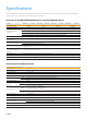
Datasheet


17
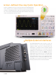
RIGOL
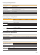
Setup Hold
When the setup time or hold time between the input clock signal and the data signal is smaller than the specified time (8
ns ~ 1 s)
Source channel: CH1 ~ CH4, D0 ~ D15
Nth Edge
Trigger on the Nth edge that appears after the specified idle time. The edge can be specified as Rising or Falling
Source channel: CH1 ~ CH4, D0 ~ D15
RS232/UART
(Option)
DS7000-COMP option
Trigger on the Start, Error, Check Error, or Data frame of the RS232/UART bus (up to 20Mb/s)
Source channel: CH1 ~ CH4, D0 ~ D15
I2C (Option)
DS7000-EMBD option
Trigger on the Start, Stop, Restart, MissedACK, Address (7 bits, 8 bits, or 10 bits), Data, or Address Data of the I2C bus
Source channel: CH1 ~ CH4, D0 ~ D15
SPI (Option)
DS7000-EMBD option
Trigger on the specified pattern of the specified data width (4 ~ 32) of SPI bus. CS and Timeout are supported
Source channel: CH1 ~ CH4, D0 ~ D15
CAN (Option)
DS7000-AUTO option
Trigger on the start of a frame, end of a frame, Remote ID, Overload, Frame ID, Frame Data, Data&ID, Frame Error,
Answer Error, Check Error, Format Error, and Random of the CAN signal (up to 5Mb/s). The supported CAN bus signal
types include CAN_H, CAN_L, TX/RX, and DIFF
Source channel: CH1 ~ CH4, D0 ~ D15
FlexRay (Option)
DS7000-FLEX option
Trigger on the specified position (TSS End, FSS_BSS End, FES End and DTS End), frame (Invalid, Syn, Start and All),
symbol (CAS/MTS and WUS), error (Head CRC Err, Tail CRC Err, Decode Err, and Random Err.) of the FlexRay signal (up
to 10 Mb/s)
Source channel: CH1 ~ CH4, D0 ~ D15
LIN (Option)
DS7000-AUTO option
Triggers on the Sync, ID, Data (length settable), Data&ID, Wakeup, Sleep, and Error of the LIN bus signal (up to 20 Mb/s)
Source channel: CH1 ~ CH4, D0 ~ D15
I2S (Option)
DS7000-AUDIO option
Triggers on 2's complement data of audio left channel, right channel, or either channel (=, ≠, >, <, <>, ><). The
available alignment modes include I2S, LJ, and RJ
Source channel: CH1 ~ CH4, D0 ~ D15
MIL-STD-1553
(Option)
DS7000-AERO option
Triggers on the sync (Data Sync, Cmd Sync, and All Sync) field, Data word, command word, status word, and Error (Sync
Error and Check Error) of the MIL-STD-1553 bus
Source channel: CH1 ~ CH4
Search and Navigation
Search, Navigation, and Table
Type Edge, Pulse, Runt, Slope, RS232, I2C and SPI
Source Any analog channel
Copy Copy the search settings to the trigger settings, and copy from the trigger settings
Result Display Event table or navigation. Go to the specific event through the event table index
Navigation
Memory playing: view the memory waveforms with the navigation keys by scrolling through stored waveform data,
supporting viewing at three speeds
ZOOM playing: view the details of waveforms with the navigation keys by panning the ZOOM window automatically,
supporting viewing at three speeds
Recording playback: play back the recorded waveforms with the navigation keys
Event navigation: use the navigation keys to scroll through the event search results
Waveform Measurement
Waveform Measurement
Cursor
Number of
Cursors
2 pairs of XY cursors
Manual Mode
Voltage deviation between cursors (△Y)
Time deviation between cursors (△X)
Reciprocal of △X (Hz) (1/△X)
Track Mode
Fix Y-axis to track X-axis waveform point's voltage and time values
Fix X-axis to track Y-axis waveform point's voltage and time values
Auto
Measurement
Allows to display cursors during auto measurement
XY Mode
Measures the voltage parameters of the corresponding channel waveforms in XY time base
mode.
X = Channel 1, Y = Channel 2