RIGOL User’s Guide DSA800 Series Spectrum Analyzer Aug. 2016 RIGOL TECHNOLOGIES, INC.
RIGOL Guaranty and Declaration Copyright © 2014 RIGOL TECHNOLOGIES, INC. All Rights Reserved. Trademark Information RIGOL is a registered trademark of RIGOL TECHNOLOGIES, INC. Publication Number UGD07109-1110 Software Version DSA815:00.01.17 DSA832/DSA875:00.01.03 Software upgrade might change or add product features. Please acquire the latest version of the manual from RIGOL website or contact RIGOL to upgrade the software. Notices RIGOL products are covered by P.R.C.
RIGOL Safety Requirement General Safety Summary Please review the following safety precautions carefully before putting the instrument into operation so as to avoid any personal injury or damage to the instrument and any product connected to it. To prevent potential hazards, please follow the instructions specified in this manual to use the instrument properly. Use Proper Power Cord. Only the exclusive power cord designed for the instrument and authorized for use within the local country could be used.
RIGOL Do Not Operate Without Covers. Do not operate the instrument with covers or panels removed. Do Not Insert Objects Into the Air Outlet. Do not insert objects into the air outlet, as doing so may cause damage to the instrument. Use Proper Fuse. Please use the specified fuses. Avoid Circuit or Wire Exposure. Do not touch exposed junctions and components when the unit is powered on. Do Not Operate With Suspected Failures.
RIGOL Prevent Electrostatic Impact. Operate the instrument in an electrostatic discharge protective environment to avoid damage induced by static discharges. Always ground both the internal and external conductors of cables to release static before making connections. Use the Battery Properly. Do not expose the battery (if available) to high temperature or fire. Keep it out of the reach of children. Improper change of a battery (lithium battery) may cause an explosion. Use the RIGOL specified battery only.
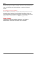
RIGOL Safety Notices and Symbols Safety Notices in this Manual: WARNING Indicates a potentially hazardous situation or practice which, if not avoided, will result in serious injury or death. CAUTION Indicates a potentially hazardous situation or practice which, if not avoided, could result in damage to the product or loss of important data. Safety Terms on the Product: DANGER WARNING CAUTION It calls attention to an operation, if not correctly performed, could result in injury or hazard immediately.
RIGOL Allgemeine Sicherheits Informationen Überprüfen Sie diefolgenden Sicherheitshinweise sorgfältigumPersonenschädenoderSchäden am Gerätundan damit verbundenen weiteren Gerätenzu vermeiden. Zur Vermeidung vonGefahren, nutzen Sie bitte das Gerät nur so, wiein diesem Handbuchangegeben. Um Feuer oder Verletzungen zu vermeiden, verwenden Sie ein ordnungsgemäßes Netzkabel. Verwenden Sie für dieses Gerät nur das für ihr Land zugelassene und genehmigte Netzkabel. Erden des Gerätes.
RIGOL Betreiben Sie das Gerät nicht geöffnet. Der Betrieb mit offenen oder entfernten Gehäuseteilen ist nicht zulässig. Nichts in entsprechende Öffnungen stecken (Lüfter z.B.) Passende Sicherung verwenden. Setzen Sie nur die spezifikationsgemäßen Sicherungen ein. Vermeiden Sie ungeschützte Verbindungen. Berühren Sie keine unisolierten Verbindungen oder Baugruppen, während das Gerät in Betrieb ist. Betreiben Sie das Gerät nicht im Fehlerfall.
RIGOL Funktionsstörungen durch ESD zu vermeiden. Erden Sie vor dem Anschluß immer Innen- und Außenleiter der Verbindungsleitung, um statische Aufladung zu entladen. Die richtige Verwendung desAkku. Wenneine Batterieverwendet wird, vermeiden Sie hohe Temperaturen bzw. Feuer ausgesetzt werden. Bewahren Sie es außerhalbder Reichweitevon Kindern auf. UnsachgemäßeÄnderung derBatterie (Anmerkung: Lithium-Batterie) kann zu einer Explosion führen. VerwendenSie nur von RIGOL angegebenenAkkus. Sicherer Transport.
RIGOL Sicherheits Begriffe und Symbole Begriffe in diesem Guide: WARNING Die Kennzeichnung WARNING beschreibt Gefahrenquellen die leibliche Schäden oder den Tod von Personen zur Folge haben können. CAUTION Die Kennzeichnung Caution (Vorsicht) beschreibt Gefahrenquellen die Schäden am Gerät hervorrufen können. Begriffe auf dem Produkt: DANGER WARNING CAUTION weist auf eine Verletzung oder Gefährdung hin, die sofort geschehen kann.
RIGOL Care and Cleaning Care Do not store or leave the instrument where it may be exposed to direct sunlight for long periods of time. Cleaning Clean the instrument regularly according to its operating conditions. 1. Disconnect the instrument from all power sources. 2. Clean the external surfaces of the instrument with a soft cloth dampened with mild detergent or water. When cleaning the LCD, take care to avoid scarifying it. CAUTION To avoid damage to the instrument, do not expose it to caustic liquids.
RIGOL Environmental Considerations The following symbol indicates that this product complies with the WEEE Directive 2002/96/EC. Product End-of-Life Handling The equipment may contain substances that could be harmful to the environment or human health. To avoid the release of such substances into the environment and avoid harm to human health, we recommend you to recycle this product appropriately to ensure that most materials are reused or recycled properly.
RIGOL XII User’s Guide for DSA800 Series
RIGOL DSA800 Series Overview DSA800 series spectrum analyzers which are small, light and cost-effective, are portable spectrum analyzers designed for starters. Configured with easy-to-operate numeric keyboard, high-resolution color LCD display and various remote communication interfaces, they can be widely used in various fields, such as education, company research and development as well as industrial manufacture. Main features: The highest frequency: 1.5 GHz/3.2 GHz/7.
RIGOL Document Overview Topics in this manual: Chapter 1 Quick Start This chapter introduces the front/rear panel and user interface as well as announcements during first use of the analyzer. Chapter 2 Front Panel Operation This chapter gives detailed function descriptions of the front panel keys with their associated menu keys. Chapter 3 Remote Control This chapter shows how to control the analyzer in remote mode.
RIGOL Format conventions in this manual: 1. Keys: The keys at the front panel are usually denoted by the format of “Key name (Bold) +textbox”. For example, FREQ denotes the FREQ key. 2. Menu keys: The menu softkeys are usually denoted by the format of “Menu word (Bold) +character shading”. For example, Center Freq denotes the center frequency menu item under the FREQ function key. 3.
RIGOL Contents Contents Guaranty and Declaration......................................................................... I Safety Requirement................................................................................. II General Safety Summary........................................................................... II Safety Notices and Symbols ...................................................................... V Allgemeine Sicherheits Informationen .............................................
Contents RIGOL To Replace the Fuse .............................................................................1-31 Chapter 2 Front Panel Operation ........................................................ 2-1 Basic Settings ....................................................................................... 2-2 FREQ ............................................................................................. 2-2 SPAN .....................................................................................
RIGOL Contents Messages .............................................................................................. 4-4 Information Message ....................................................................... 4-6 Error Message ................................................................................. 4-9 Status Message ............................................................................. 4-22 Chapter 5 Specifications ....................................................................
Chapter 1 Quick Start RIGOL Chapter 1 Quick Start This chapter guides users to quickly get familiar with the appearance, dimensions, front/ rear panel and the user interface, as well as announcements during first use of DSA800 series spectrum analyzer.
RIGOL Chapter 1 Quick Start General Inspection 1. Inspect the packaging If the packaging has been damaged, do not dispose the damaged packaging or cushioning materials until the shipment has been checked for completeness and has passed both electrical and mechanical tests. The consigner or carrier shall be liable for the damage to the instrument resulting from shipment. RIGOL would not be responsible for free maintenance/rework or replacement of the instrument. 2.
RIGOL Chapter 1 Quick Start Appearance and Dimensions Figure 1-1 Front View Unit: mm Figure 1-2 Side View Unit: mm User’s Guide for DSA800 Series 1-3
RIGOL Chapter 1 Quick Start To Prepare for Use To Adjust the Supporting Legs Users can unfold the supporting legs to use them as stands to tilt the instrument upwards for easier operation and observation. Users can also fold the supporting legs when the instrument is not in use for easier storage or shipment.
RIGOL Chapter 1 Quick Start To Connect to Power Please use the power cord provided with the accessories to connect the spectrum analyzer to AC power source as shown in the figure below. The AC power supply specification of this spectrum analyzer is 100-240 V, 45-440 Hz. The power consumption of the instrument cannot exceed 50 W.
RIGOL Chapter 1 Quick Start Power-on Inspection After connecting the instrument to power source correctly, press at the front panel to start the spectrum analyzer. Following the start-up screen which shows the start-up initialization process information, the sweep curve is displayed. Self-calibration After the instrument starts, execute self-calibration. Press System Calibrate Cal Now and the instrument will perform self-calibration using the internal calibration source.
RIGOL Chapter 1 Quick Start Front Panel The front panel of DSA800 is as shown in the figure below. 1 3 2 14 4 13 5 12 6 11 10 9 Figure 1-5 Front Panel 8 7 Table 1-1 Front Panel Description NO. Description NO.
RIGOL Chapter 1 Quick Start Front Panel Function Keys Figure 1-6 Function Key Area Table 1-2 Function keys description Key Description FREQ Set the center, start and stop frequency, etc; enable the signal tracking function. SPAN Set the frequency span of the sweep. AMPT Set the reference level, RF attenuator, scale and the unit of Y-axis, etc. Set the reference level offset, maximum mixing level and input impedence. Execute auto scale and auto range as well as turn on the RF preamplifier.
RIGOL Chapter 1 Quick Start Demod Set the demodulation function. Marker Read the amplitude, frequency and sweep time of a certain point on the trace via marker. Marker—> Set other system parameters on the basis of the current marker value. Marker Fctn Special functions of the marker such as noise marker, N dB bandwidth measurement and frequency counter. Peak Open the peak search menu and search for peaks immediately. System Set the system parameters. Print Setup Set the print parameters.
RIGOL Chapter 1 Quick Start Front Panel Key Backlight The on/off state and the color of the backlights of some keys at the front panel indicate the working state of the spectrum analyzer. The states are as listed below. 1. Power Switch Flash on and off alternatively, in breathing state: indicate the unit is in stand-by state. Constant on: indicate the instrument is in normal operating state. 2.
RIGOL Chapter 1 Quick Start Front Panel Connectors USB Host Earphone jack Tracking generator output RF input Figure 1-7 Front Panel Connectors 1. USB Host The analyzer can serve as a “host” device to connect external USB devices. This interface is available for USB storage devices and USB-GPIB interface converter.
RIGOL 3. Chapter 1 Quick Start GEN OUTPUT 50Ω The output of the tracking generator can be connected to a receiver through a cable with an N male connector. The tracking generator is only available for DSA815-TG/DSA832-TG/DSA875-TG. CAUTION To avoid damage to the tracking generator, the reverse power cannot exceed +10 dBm when the frequency is lower than 10 MHz; the reverse power cannot exceed +20 dBm when the frequency is greater than 10 MHz. The reverse DC voltage cannot exceed 50 V. 4.
RIGOL Chapter 1 Quick Start To Use the Numeric Keyboard DSA800 provides a numeric keyboard at the front panel (as shown in the figure below). The numeric keyboard which supports the Chinese characters, English uppercase/lowercase characters, numbers and common symbols (including decimal point, #, space and +/-) are mainly used to edit file or folder name (refer to “To Input Filename”) and set parameters (refer to “Parameter Setting”).
RIGOL Chapter 1 Quick Start is the multiplexing key for 0 and space. Press this key to input 0 in number input and space in Chinese or English input. 3. Press this key to input a decimal point at the current cursor position in number input. Press this key to input “#” in English input. This key is invalid in Chinese input. 4. When pressed during parameter editing process, the system will complete the input and insert a default unit for the parameter automatically.
RIGOL Chapter 1 Quick Start Rear Panel The rear panel of DSA800 is as shown in the figure below. 9 8 7 6 5 1 2 Figure 1-9 Rear Panel 3 4 1. AC Power Connector The AC power supply specification of this spectrum analyzer is 100-240 V, 45-440 Hz. 2. Fuse Seat You can replace the fuse. DSA800 supports 250V AC, T2A fuse. 3. Security Lock Hole If needed, you can use a security lock (buy it yourself) to lock the analyzer to a desired location. 4.
RIGOL Chapter 1 Quick Start connector, this signal is used as the external reference source and “Ext Ref” is displayed in the status bar of the user interface. When the external reference is lost, transfinite or not connected, the instrument swithes to its internal reference source automatically and “Ext Ref” on the screen disappears. The [10MHz IN] and [10MHz OUT] connectors are usually used to build synchronization among multiple instruments. 6.
RIGOL Chapter 1 Quick Start User Interface 1 12 2 13 14 3 15 16 17 4 5 6 7 8 18 1 19 9 10 11 31 32 33 20 34 35 1 36 37 38 39 40 41 42 30 29 28 27 26 25 24 23 22 21 Figure 1-10 User Interface Table 1-3 User interface labels NO.
RIGOL Chapter 1 Quick Start connection is in process. : denote the connection succeeds, the print finishes or the printer is idle. : displayed alternatively, denote the print is in process. : denote the print has been paused. 7 Print process Show the current print copy and total print copies. 8 USB storage device status is displayed when USB storage device is installed. 9 Operation status Display “Local” (in local mode) or “Rmt” (in remote mode). 10 Menu title Function of the current menu.
RIGOL Chapter 1 Quick Start symbol mode. 26 VBW Video bandwidth. 27 Spectrum line display area Display the spectrum line. 28 RBW Resolution bandwidth. 29 Center or start frequency The frequency range of the current sweep channel can be expressed by the combination of center frequency and span or the combination of start frequency and stop frequency. 30 Y scale Label of Y scale. 31 Parameter status Icons on the left side of the screen indicate the status of system parameters.
RIGOL Chapter 1 Quick Start Menu Operation There are 7 types of menus according to their operation modes. Each type of menu and its operation method are introduced below. 1. Parameter Input When selected, use the numeric keys to modify the parameters directly. For example, select Center Freq, input the desired figure and press Enter to change the center frequency. 2. State Switching Press the corresponding menu key to switch between the sub-options.
RIGOL Chapter 1 Quick Start 5. Direct Execution Press the key to execute the corresponding function. For example, press Peak->CF to execute a peak search and set the center frequency of the analyzer to the frequency of the current peak signal. 6. Function Switch + Parameter Input Press the corresponding menu key to switch between functions; change the parameter directly using the numeric keys.
RIGOL Chapter 1 Quick Start Parameter Setting Users can enter the desired parameter values using the numeric keys, knob or direction keys. This section describes the three methods of parameter setting through an example (to set the center frequency to 800 MHz). 1. Use the numeric keyboard 1) Press FREQ Center Freq; 2) Input 800 using the numeric keys; 3) Select the desired unit (MHz) from the popup menu. 2.
RIGOL Chapter 1 Quick Start Figure 1-12 Direction Keys Note: In the storage function, the direction keys can also be used to select the current path or file.
RIGOL Chapter 1 Quick Start To Input Filename DSA800 supports filenames consisting of Chinese characters, English letters, numbers and #. 1. Enter the filename input interface Press Storage and select the desired file type and storage location. Then press Save to enter the filename input interface. You can press to switch among English, Chinese and number input modes.
RIGOL Chapter 1 Quick Start Numbers Entered Number Input Mode (c) Number Input Mode Figure 1-13 Filename Input Interface Tip: If a USB storage device is currently connected, the instrument will also enter the filename input interface when 2. Input Chinese Filename 1) 2) 3) 4) 3. is pressed. Press to switch to Chinese input mode. At this point, the corresponding label is displayed at the lower right corner of the filename input interface.
RIGOL 2) 3) Chapter 1 Quick Start switch between upper and lower cases. At this point, the corresponding label is displayed at the lower right corner of the filename input interface. Press the key of the desired letter. At this point, the letters available are displayed in the letter selecting area. Press this key repeatedly or retate the knob until the desired letter is selected (the background color of the letter becomes brown). Then press Enter to input the desired letter.
RIGOL Chapter 1 Quick Start To Lock the Keyboard You can lock one or more function keys or all keys (except the power switch) and knob at the front panel using keyboard lock commands. 1. The intrudction of keyboard lock commands :SYSTem:KLOCk ON|OFF|1|0, :SYSTem:KLOCk? /* Lock or unlock the specified key*/ /* Query whether the specified key is locked*/ Wherein, the parameter is used to specify the keys. The range of this parameter is as follows.
RIGOL Chapter 1 Quick Start To Use the Built-in Help The built-in help system provides information about every function key at the front panel and every menu softkey. 1. How to acquire built-in help Press Help and a prompt about how to obtain help information will be shown at the center of the screen. Then, press the key that you want to get help of and the relevant help information will be shown at the center of the screen. 2.
RIGOL Chapter 1 Quick Start Figure 1-14 The Built-in Help Interface User’s Guide for DSA800 Series 1-29
RIGOL Chapter 1 Quick Start To Use the Security Lock If necessary, use a security lock to lock the analyzer in a desired location. As shown in the figure below, align the lock with the lock hole and plug it into the lock hole vertically, turn the key clockwise to lock the instrument and then pull the key out. Key Security Lock Security Lock Hole Figure 1-15 To Use the Security Lock Note: Please do not insert other articles into the security lock hole to avoid damaging the instrument.
RIGOL Chapter 1 Quick Start To Replace the Fuse Please replace the old fuse with specified fuse according to the following steps when needed: 1. Turn off the instrument, cut off the power and remove the power cord. 2. Use a small straight screw driver to prize out the fuse seat. 3. Take out the fuse seat. 4. Replace the old fuse with a specified fuse. 5. Install the fuse seat.
Chapter 2 Front Panel Operation RIGOL Chapter 2 Front Panel Operation This chapter describes in detail the function keys at the front panel and the associated functions.
RIGOL Chapter 2 Front Panel Operation Basic Settings FREQ Set the frequency parameters of the analyzer. The analyzer sweeps within a specified frequency range and restarts sweeping every time the frequency parameters are modified. The frequency range of a channel can be expressed by either of two groups of parameters: Start Frequency and Stop Frequency ( f start / f stop ); or Center Frequency and Span ( f center / f span ).
Chapter 2 Front Panel Operation RIGOL Center Freq Set the center frequency of the current channel. Press this key to switch to center frequency/span input mode. The center frequency and span values are displayed at the lower left and right sides of the grid respectively. Key Points: The start and stop frequencies vary with the center frequency when the span is constant. Changing the center frequency horizontally shifts the current channel and the adjustment is limited by the specified frequency range.
RIGOL Chapter 2 Front Panel Operation span would affect other system parameters. For more details, please refer to “Span”. In Zero Span mode, the start frequency, stop frequency and center frequency are always the same. If one is changed, the others are updated to match. You can modify this parameter using the numeric keys, knob or direction keys. Refer to “Parameter Setting” for more details. Table 2-2 Start Frequency Parameter Explanation Default 0 GHz Range* 0 Hz to 7.
Chapter 2 Front Panel Operation RIGOL Table 2-3 Stop Frequency Parameter Explanation Default 7.5 GHz Range* 0 Hz to 7.5 GHz Unit GHz, MHz, kHz, Hz Knob Step Span > 0, step = Span/200 Span = 0, step = VBW/100 Min = 1 Hz Direction Key Step CF step Note: *The range is from 100 Hz to 7.5 GHz in non-zero span. Freq Offset You can set a frequency offset value to account for frequency conversions between the device under test and the input terminal of the spectrum analyzer.
RIGOL Chapter 2 Front Panel Operation CF Step Set the step of center frequency. Changing the center frequency in a fixed step continuously switches the channel to be measured. Key Points: The CF step can be set in “Manual” or “Auto” mode. In Auto mode, the CF step is 1/10 of the span in Non-zero span mode or equals the RBW while in Zero span mode; in Manual mode, you can set the step using the numeric keys.
RIGOL Chapter 2 Front Panel Operation Start Execute a sweep Active Marker exists? Y N Search for peak and mark it as Marker Search for and mark the frequency point (variation < 3dB) near the Marker Set marker frequency to center freq Execute the next sweep Figure 2-1 Process of Signal Track Key Points: When Signal Track is turned on, the ST (Signal Track) icon is highlighted in the status bar at the left of the screen.
RIGOL Chapter 2 Front Panel Operation Peak -> CF Execute a peak search and use the frequency of the current peak as the center frequency (CF) of the analyzer. The function is invalid in Zero Span mode.
Chapter 2 Front Panel Operation RIGOL CF -> Step Set the current center frequency as the CF step. At this point, the CF step will switch to "Manual" mode automatically. This function is usually used with channel switching. Take harmonic waveform measurement for example: locate a signal at the center frequency of a channel, execute CF-> Step and then press the down direction key continuously to measure each order of harmonic in sequence. SPAN Set the span of the analyzer.
RIGOL Chapter 2 Front Panel Operation For more details, please refer to “Parameter Setting”. Table 2-6 Span Parameter Explanation Default 7.5 GHz Range* 0 Hz to 7.5 GHz Unit GHz, MHz, kHz, Hz Knob Step Span/200, Min = 1 Hz Direction Key Step in 1, 2, 5 sequence Note: *0 Hz is available only in zero span. Full Span Set the span of the analyzer to the maximum. Zero Span Set the span of the analyzer to 0 Hz.
Chapter 2 Front Panel Operation RIGOL Zoom In Set the span to half of its current value. At this point, the signal on the screen is zoomed in to observe signal details. Zoom Out Set the span to twice the current value. At this point, the signal on the screen is zoomed out to gain more information about the signal. Last Span Set the span to the previous span setting. X Scale Select the scale type of X-axis to Lin or Log. The default is Lin.
RIGOL Chapter 2 Front Panel Operation AMPT Set the amplitude parameters of the analyzer. Through modifying these parameters, signals under measurement can be displayed in a proper mode for easier obsercation and minimum error. Auto Scale This function enables the readout resolution of the Y-axis to be the maximum possible while at the same time ensures the completeness of the signal.
RIGOL Chapter 2 Front Panel Operation Figure 2-5 After Auto Scale Ref Level Set the maximum power or voltage can be currently displayed in the window. The value is displayed at the upper left corner of the screen grid. Key Points: The maximum reference level available is affected by the maximum mixing level, input attenuation and preamplifier.
RIGOL Chapter 2 Front Panel Operation Table 2-7 Reference Level Parameter Explanation Default 0 dBm Range -100 dBm to 20 dBm Unit dBm, -dBm, mV, uV Knob Step In Log scale mode, step = Scale/10 In Lin scale mode, step = 0.1 dBm Direction Key Step In Log scale mode, step = Scale In Lin scale mode, step = 1 dBm Input Atten Set the front attenuator of the RF input in order to ensure big signals (or small signals) to pass through the mixer with low distortion (or low noise).
Chapter 2 Front Panel Operation RIGOL Key Points: By changing the scale, the amplitude range available is adjusted. The range of the amplitude that can be displayed: Minimum: reference level – 10 × the current scale value Maximum: the reference level. You can modify this parameter using the numeric keys, knob or direction keys. For more details, please refer to “Parameter Setting”. Table 2-9 Scale Parameter Explanation Default 10 dB Range 0.
RIGOL Chapter 2 Front Panel Operation Units Set the unit of the Y-axis to dBm, dBmV, dBuV, Volts or Watts. Wherein, dBm, dBmV and dBuV are for Log scale; Volts and Watts are for Linear scale. The default is dBm. Key Points: The conversion relationships between units are as follows. Volts 2 1 dBm = 10log × R 0.001W (2-4) Volts dBµV = 20log 1µV (2-5) Volts dBmV = 20log 1mV (2-6) Volts 2 R (2-7) Watts = Wherein, R denotes the reference resistance.
Chapter 2 Front Panel Operation RIGOL Table 2-10 Reference Level Offset Parameter Explanation Default 0 dB Range -300 dB to 300 dB Unit dB Knob Step N/A Direction Key Step N/A Auto Range Adjust the amplitude parameters within the current span range automatically in order to display the whole signal optimally on the screen.
RIGOL Chapter 2 Front Panel Operation Figure 2-7 After Auto Range Key Points: Unlike Auto Scale, this function can solve the problem of signal overrange due to parameter settings and adjust the maximum mixing level according to the signal under measurement. Unlike Auto, this function adjusts the signal within the current channel and does not modify the channel frequency setting. While, Auto will search for signal within the full frequency range and locate the signal at the center frequency.
RIGOL Chapter 2 Front Panel Operation Start Peak Search Peak > Ref Level? N Y Adjust Ref Level Large signal? N Y Decrease maximum mixing level Increase maximum mixing level Auto Scale Stop Figure 2-8 Process of Auto Range RF Preamp Turn on or off the preamplifier located at the front of the RF signal path. When the signal under measurement is small, turning on the preamplifier can reduce the displayed average noise level; therefor, you can distinguish small signals from the noise.
RIGOL Chapter 2 Front Panel Operation Correction Correct the amplitude in order to compensate for the gain or loss from external devices such as Antenna and Cable. When using this function, you can view the correction data table and save or load the current correction data. When amplitude correction is turned on, both the trace and related measurement results will be corrected; the corresponding icon the screen. is highlighted in the status bar at the left of 1.
Chapter 2 Front Panel Operation RIGOL Table 2-11 Edit menus of amplitude correction Menu Explanation Point Create or edit the data point of a correction factor. Range: 1 to 200 Frequency Set the frequency of the specified point in the correction factor. Amplitude Set the amplitude correction of the specified point in the correction factor. Range: -120 dB to 100 dB Del Point Delete the specified point data in the correction factor: frequency and amplitude correction. 4.
RIGOL Chapter 2 Front Panel Operation MaxMixL Set the max input level of the mixer according to the magnitude of the signal. Key Points: For a larger input signal, select a smaller maximum mixing level to increase the input attenuation and reduce the distortion of the signal; for a smaller input signal, select a larger maximum mixing level to reduce the input attenuation and noise. Parameters in inequality (2-3) are always modified on the basis of the maximum mixing level.
Chapter 2 Front Panel Operation RIGOL Sweep and Function Settings BW/Det Set the RBW (Resolution Bandwidth), VBW (Video Bandwidth) and detector type parameters of the analyzer. RBW Set the desired resolution bandwidth in order to distinguish between signals which are close in frequency. Key Points: Reducing RBW will increase the frequency resolution, but will increase the sweep time (Sweep Time is affected by a combination of RBW and VBW when it is in Auto mode).
RIGOL Chapter 2 Front Panel Operation VBW Set the desired video bandwidth in order to filter out the noise outside the video band. Key Points: Reducing the VBW will smooth the spectrum line to differentiate small signals from noise, but will increase the sweep time (Sweep Time is affected by a combination of RBW and VBW when it is in Auto mode). VBW varies with RBW when it is set to Auto. While in Manual mode, VBW is not affected by RBW.
Chapter 2 Front Panel Operation RIGOL Table 2-15 V/R Ratio Parameter Explanation Default 1 Range 0.0000010 to 30000 Unit N/A Knob Step in 1, 3, 10 sequence Direction Key Step in 1, 3, 10 sequence Detector Type The analyzer displays the sweeped signal on the screen in the form of trace. For each trace point, the analyzer always captures all the data within a specific time interval and processes (Peak, Average,etc.
RIGOL Chapter 2 Front Panel Operation 3. Sample For each trace point, Sample detector displays the transient level corresponding to the central time point of the corresponding time interval. This detector type is applicable to noise or noise-like signal. 4.
Chapter 2 Front Panel Operation 7. RIGOL Quasi-Peak (an option for DSA800) It is a weighted form of peak detector. For each data point, the detector detects the peaks within the corresponding time interval. The peaks detected are weighted using circuit with specified charge and discharge structures as well as the display time constant specified in the CISPR Publication 16 standards and the result is displayed. Quasi-Peak detector is applicable to EMI testing.
RIGOL Chapter 2 Front Panel Operation Sweep/Trig Set parameters about the Sweep and Trigger functions, including sweep time, auto sweep time, sweep mode, number of sweep, trigger type, etc. Sweep Time Set the time needed for the spectrum analyzer to finish a sweep within the span range. The sweep time can be set in “Auto” or “Manual” mode and the default is “Auto”.
RIGOL Chapter 2 Front Panel Operation Auto SWT Set the auto setting method of the sweep time to “Normal” or “Accy”. The sweep will be faster if “Normal” is selected; while in “Accy” type, higher measurement precision can be obtained. Mode Set the sweep mode to “Single” or “Cont”. The default is “Cont”. The corresponding icon of the sweep mode will be displayed in the status bar at the left side of the screen. Single Continuous 1. Single Set the sweep mode to “Single”.
RIGOL Chapter 2 Front Panel Operation Select “Cont” Y N Single sweep status? Enter continuous sweep mode and wait for trigger condition Sweep again and wait for trigger condition Figure 2-9 Process of Continuous Sweep Single In single sweep mode, this menu is used to execute trigger initialization. After that, the analyzer will execute the specified number of sweeps (or measurements) if the trigger conditions are satisfied.
RIGOL Chapter 2 Front Panel Operation Press “Single” N Y Measurement status? N Single sweep mode? Enter single sweep mode and wait for trigger condition Y Sweep again and wait for trigger condition N Single sweep mode? Enter single sweep/ measurement mode and wait for trigger condition Y Wait for trigger condition and make single measurement again Figure 2-10 Process of Single Sweep Numbers Set the number of sweeps for a single sweep.
RIGOL Chapter 2 Front Panel Operation Trig Type The trigger type can be Free Run, Video or External. The corresponding icon of the trigger type will be displayed in the status bar at the left of the screen. 1. Free Run The trigger conditions are satisfied at any time and the analyzer generates trigger signals continuously. 2. Video A trigger signal will be generated when the system detects a video signal of which the voltage exceeds the specified video trigger level.
RIGOL Chapter 2 Front Panel Operation Table 2-18 Trigger level Parameter Explanation Default 0 dBm Range -300 dBm to 50 dBm Unit* dBm Knob Step 1 dBm Direction Key Step 10 dBm Note: *It is related to the specified unit of Y-axis. 2. Edge Set the trigger edge in external trigger to the rising (Pos) or falling (Neg) edge of the pulse. Note: When “Free Run” is selected, Trig Setup is grayed out and disabled. Points Set the desired points for every sweep.
RIGOL Chapter 2 Front Panel Operation Trace/P/F The sweep signal is displayed as a trace on the screen. In addition, DSA800 provides the Pass/Fail (P/F) test function. Trace/P/F is used to set parameters related to the trace and P/F test. Select Trace DSA800 allows for up to four traces to be displayed at the same time. Each trace has its own color (Trace 1 - yellow, Trace 2 - purple, Trace 3 - light blue and Trace 4 - green).
Chapter 2 Front Panel Operation RIGOL of each point on the trace. 2. Max Hold Display the maximum from multiple sweeps for each point of the trace and update the data if a new maximum is generated in successive sweeps. 3. Min Hold Display the minimum from multiple sweeps for each point of the trace and update the data if a new minimum is generated in successive sweeps. 4. Video Avg Display the logarithmic average of data from multiple sweeps for each point of the trace.
RIGOL Chapter 2 Front Panel Operation Table 2-20 Average times Parameter Explanation Default 100 Range 1 to 1000 Unit N/A Knob Step N/A Direction Key Step N/A Trace Math 1. Function Set the computational method of the math trace. A-B: subtract Trace B from A A+Constant: add a constant to Trace A A-Constant: subtract a constant from Trace A 2. A Select “T1”, “T2” or “T3”. Assign a value to A from Trace1, Trace 2 or Trace 3. The default is Trace 1 (T1). 3. B Select “T1”, “T2” or “T3”.
Chapter 2 Front Panel Operation 5. RIGOL Operate Enable or disable the display of the math trace and the default is Off. Note: This menu is valid only when A or B is set to the selected type of trace. Blank All Disable all the traces displayed on the screen. This operation will stop the current advanced measurement as there is not valid data source. Pass/Fail DSA800 supports the Pass/Fail test function. In this function, the measured curve is compared with the pre-edited curve.
RIGOL Chapter 2 Front Panel Operation Result: The results of Pass/Fail test contain the pass number and the pass ratio. 1. Switch Turn on or off the Pass/Fail test function and the default is “Off”. When the function is enabled, the system changes to split-screen display. At this point, T2 and T3 are used for marking the upper and lower limits separately. 2. Settings Limit: select the desired limit line (upper or lower) for editing. Then, press Edit to set the limit conditions.
RIGOL Chapter 2 Front Panel Operation X Axis: set the X-axis unit to frequency or time unit. Note that all the points of the current limit line will be deleted when the X-axis unit changes. Freq Interp: set the Freq Interp to Log or Lin. In Log mode, both the frequency and amplitude use Log unit to make interpolation operation; in Lin mode, the frequency uses a Lin unit and the amplitude uses a Log unit for interpolation operation.
RIGOL 7. Chapter 2 Front Panel Operation Single In single mode, the analyzer stops after the specified number of tests. After this, every time when Single is pressed, the system executes the specified number of tests and updates the test data. Average Reset Achieve the recalculation of the trace average. Note: You can use this function only when the trace type is set to “Video Avg” or “Power Avg”.
Chapter 2 Front Panel Operation RIGOL TG Set the parameter related to the tracking generator (TG). The tracking generator provides two working modes: Power Sweep output (when Power Sweep is On) and Fixed Power output (when Power Sweep is Off). The TG function is only valid when your analyzer is DSA815-TG/DSA832-TG/DSA875-TG. TG TG is used to enable or disable the TG.
RIGOL Chapter 2 Front Panel Operation TG Lvl Offset Assign a certain offset to the output power of the TG when gains or losses occur between the TG output and external device in order to display the actual power value. Key Points: This parameter only changes the readout of the TG output power, rather than the actual value of it. The offset could be either a positive (gain in the external output) or a negative (loss in the external output).
RIGOL Chapter 2 Front Panel Operation Ampl (dBm) Power Range TG Level Start Freq TG Output Stop Freq Freq (Hz) Figure 2-12 Power Sweep Power Range (Only for DSA815) Set the output power range of the TG in power sweep mode. This parameter together with the TG level forms the boundary parameters in power sweep mode. You can use the numeric keys, knob or direction keys to modify this parameter. For more details, please refer to “Parameter Setting”.
RIGOL Chapter 2 Front Panel Operation Normalize Nomalization can eliminate the error of TG Level. Before using this function, connect the [GEN OUTPUT 50Ω] output terminal of the TG with the [RF INPUT 50Ω] input terminal of the analyzer. 1. Stor Ref Save the data of Trace 1 to Trace 3 as the reference value for normalization. This operation should be done before you enable the normalization. 2. Normalize Enable or disable the normalization.
RIGOL Chapter 2 Front Panel Operation by adjusting the reference position when normalization is enabled. The function of this menu is similar to that of Norm Ref Lvl. When it is set to 0%, the normalization reference level is displayed at the bottom of the screen grid and at the top when it is set to 100%. You can use the numeric keys, knob or direction keys to modify this parameter. For more details, please refer to “Parameter Setting”. Table 2-27 TG reference position 5.
RIGOL Chapter 2 Front Panel Operation Measurement Settings Meas Provide VSWR and various advanced measurement functions, including T-Power, ACP (Adjacent Channel Power), Chan Pwr (Channel Power), OBW (Occupied Bandwidth), EBW (Emission Bandwidth), C/N Ratio, Harmo Dist (Harmonic Distortion) and TOI (Third Order Intermodulation). For advanced measurement functions, the measurement mode can be single or continuous; you can restart, pause and resume the measurement.
Chapter 2 Front Panel Operation RIGOL 1. T-Power Ths system enters zero span mode and calculates the power within the time domain. The types of powers available include Peak, Average and RMS. Select T-Power and press Meas Setup to set the corresponding parameters. 2. ACP Measure the powers of the main channel and adjacent channels as well as the power difference between the main channel and each of the adjacent channels.
RIGOL Chapter 2 Front Panel Operation parameters. 7. Harmo Dist Measure the power of each order of harmonic and THD (total harmonic distortion) of the carrier. The highest order of harmonic available is 10 and the fundamental wave amplitude must be greater than -50 dBm; or else the measurement will be invalid. Select Harmo Dist and press Meas Setup to set the corresponding parameters. 8. TOI Measure the parameters of the TOI production of two signals with the same amplitude and similar frequency.
Chapter 2 Front Panel Operation RIGOL Meas Mode Set the measurement mode to single or continuous. In single mode, the analyzer stops after the specified number of measurements. After this, every time when Single is pressed, the system executes the specified number of measurements and updates the measurement data. In continuous mode, the analyzer measures continuously. This setting is only available for advanced measurement functions.
RIGOL Chapter 2 Front Panel Operation value of which will be displayed. RT Trace, MaxHold and 2FSK are mutually exclusive. 3. MaxHold Rst Delete the original signal and capture new signals for the max hold trace reset. The reset operation has no effect on the user settings. You can also turn max hold off and then turn it on to realizing the function of MaxHold Rst. 4. 2FSK Enable or disable the 2FSK function.
Chapter 2 Front Panel Operation RIGOL Meas Setup Open the parameter setting menu of the function selected in the Meas menu. This key is only available when a measurement function is enabled. VSWR Measurement Interface: Figure 2-13 VSWR Measurement Interface Measurerment Results: return loss, reflection coefficient and VSWR. Return Loss: the formula is RL(dB ) = 10 lg( Pi Pr ) . Wherein, RL(dB ) is the return loss, Pi is the incident power and Pr is the reflected power.
RIGOL Chapter 2 Front Panel Operation the measurement wizard at the lower side of the interface: measurement with the device under test disconnected (represented by trace 2) and measurement with the device under test connected (represented by trace 1). The return loss (represented by the math trace) is determined by the difference of the results of the two measurements and the reflection coefficient and VSWR are determined by the return loss. 1. Reset Reset the VSWR measurement parameters. 2.
RIGOL Chapter 2 Front Panel Operation You can use the numeric keys, knob or direction keys to modify this parameter.
RIGOL Chapter 2 Front Panel Operation T-Power Measurement Interface: Start Line Stop Line Measurement Control Measurement Result Measurement Parameters Figure 2-14 T-Power Measurement Interface Measurement Result: T-power, namely the power of the signal from the start line to the stop line. Measurement Parameters: average number, average mode, TP type, start line and stop line. 1. 2-54 Avg Num Specify the number of averages used when calculating the measurement result. The default is “Off”.
RIGOL Chapter 2 Front Panel Operation Table 2-29 Average Number of T-Power Measurement Parameter Description Default 10 Range 1 to 1000 Unit N/A Knob Step 1 Direction Key Step 1 2. Avg Mode Set the average operation mode to “Exp” or “Repeat” and the default is “Exp”. When “Exp” is selected, the result is the exponential average of the current N (N is specified in “Avg Num”) measurement results.
RIGOL Chapter 2 Front Panel Operation Table 2-30 Start Line for T-Power Measurement 5. Parameter Description Default 0 us Range 0 us to Stop Line Unit ks, s, ms, us, ns, ps Knob Step Sweep Time/600, Min = 1us Direction Key Step in 1-1.5-2-3-5-7.5 sequence Stop Line Set the right margin (in time unit) of T-Power measurement. The data calculated under this measurement is between the start line and stop line. You can use the numeric keys, knob or direction keys to modify this parameter.
RIGOL Chapter 2 Front Panel Operation ACP Measurement Interface: Adjacent Channel Bandwidth Channel Spacing Main Channel Bandwidth Figure 2-15 Adjacent Channel Power Measurement Interface Measurement Results: Main CH Pwr, Upper and Lower. CH Pwr: display the power within the bandwidth of the main channel. Upper: display the power of the upper channel and the power difference between the upper channel and the main channel (in dBc).
RIGOL Chapter 2 Front Panel Operation Table 2-32 Average Number for ACP Measurement Parameter Description Default 10 Range 1 to 1000 Unit N/A Knob Step 1 Direction Key Step 1 2. Avg Mode Set the average operation mode to “Exp” or “Repeat” and the default is “Exp”. When “Exp” is selected, the result is the exponential average of the current N (N is specified in “Avg Num”) measurement results.
RIGOL Chapter 2 Front Panel Operation Table 2-34 Adjacent Channel Bandwidth for ACP Measurement 5. Parameter Description Default 2 MHz Range 33 Hz to 2.5 GHz Unit GHz, MHz, kHz, Hz Knob Step Adjacent Channel BW/100, the minimum is 1 Hz Direction Key Step in 1-1.5-2-3-5-7.5 sequence CH Spacing Set the difference between the center frequency of the main channel and the center frequency of the adjacent channels.
RIGOL Chapter 2 Front Panel Operation Chan Pwr Measurement Interface: Integration Bandwidth Channel Power Span Figure 2-16 Channel Power Measurement Interface Measurement Results: channel power and power spectral density. Channel Power: power within the integration bandwidth. Power Spectral Density: power (in dBm/Hz) normalized to 1 Hz within the integration bandwidth. Measurement Parameters: average number, average mode, integration bandwidth and channel power span. 1.
RIGOL Chapter 2 Front Panel Operation Table 2-36 Average Number for Chan Power Measurement Parameter Description Default 10 Range 1 to 1000 Unit N/A Knob Step 1 Direction Key Step 1 2. Avg Mode Set the average operation mode to “Exp” or “Repeat” and the default is “Exp”. When “Exp” is selected, the result is the exponential average of the current N (N is specified in “Avg Num”) measurement results.
RIGOL Chapter 2 Front Panel Operation Table 2-38 Channel Power Span for Chan Power Measurement 2-62 Parameter Description Default 3 MHz Range 100 Hz to 7.5 GHz Unit GHz, MHz, kHz, Hz Knob Step Channel Power Span/100, the minimum is 1 Hz Direction Key Step in 1-1.5-2-3-5-7.
Chapter 2 Front Panel Operation RIGOL OBW Measurement Interface: Figure 2-17 OBW Measurement Interface Measurement Results: occupied bandwidth and transmit frequency error. Occupied Bandwidth: integrate the power within the whole span and then calculate the bandwidth occupied by the power according to the specified power ratio. Transmit Frequency Error: difference between the center frequency of the channel and the center frequency of the analyzer.
RIGOL Chapter 2 Front Panel Operation Table 2-39 Average Number for OBW Measurement Parameter Description Default 10 Range 1 to 1000 Unit N/A Knob Step 1 Direction Key Step 1 2. Avg Mode Set the average operation mode to “Exp” or “Repeat” and the default is “Exp”. When “Exp” is selected, the result is the exponential average of the current N (N is specified in “Avg Num”) measurement results.
RIGOL Chapter 2 Front Panel Operation Table 2-40 Span for OBW Measurement 5. Parameter Description Default 2 MHz Range 100 Hz to 7.5 GHz Unit GHz, MHz, kHz, Hz Knob Step OBW Span/100, the minimum is 1 Hz Direction Key Step in 1-1.5-2-3-5-7.5 sequence Power Ratio Set the percentage the signal power takes up in the whole span power. You can use the muneric keys, knob or direction keys to modify this parameter.
RIGOL Chapter 2 Front Panel Operation EBW Measurement Interface: Figure 2-18 EBW Measurement Interface Measurement Results: emission bandwidth, namely the bandwidth between two points on a signal which are X dB below the highest point within the span. During the measurement, the analyzer first determines the frequency (f0) of the maximum amplitude point within the span and then finds the two frequency points (f1 and f2) at each side of f0 at which the signal amplitude is X dB below the maximum amplitude.
RIGOL Chapter 2 Front Panel Operation Table 2-42 Average Number for EBW Measurement Parameter Description Default 10 Range 1 to 1000 Unit N/A Knob Step 1 Direction Key Step 1 2. Avg Mode Set the average operation mode to “Exp” or “Repeat” and the default is “Exp”. When “Exp” is selected, the result is the exponential average of the current N (N is specified in “Avg Num”) measurement results.
RIGOL 5. Chapter 2 Front Panel Operation EBW X dB Set the value of X dB used for EBW calculation. You can use the numeric keys, knob or direction keys to modify this parameter. Table 2-44 X dB for EBW Measurement 2-68 Parameter Description Default -10 dB Range -100 dB to -0.1 dB Unit dB Knob Step 0.
RIGOL Chapter 2 Front Panel Operation C/N Ratio Measurement Interface: Offset Frequency Noise Bandwidth Carrier Bandwidth Figure 2-19 C/N Ratio Measurement Interface Measurement Results: carrier power, noise power and C/N ratio. Carrier Power: power within the carrier bandwidth. Noise Power: power within the noise bandwidth. C/N Ratio: the ratio of the carrier power to the noise power. Measurement Parameters: average number, average mode, offset frequency, noise bandwidth and carrier bandwidth.
RIGOL Chapter 2 Front Panel Operation Table 2-45 Average Number for C/N Ratio Measurement Parameter Description Default 10 Range 1 to 1000 Unit N/A Knob Step 1 Direction Key Step 1 2. Avg Mode Set the average operation mode to “Exp” or “Repeat” and the default is “Exp”. When “Exp” is selected, the result is the exponential average of the current N (N is specified in “Avg Num”) measurement results.
RIGOL Chapter 2 Front Panel Operation Table 2-47 Noise Bandwidth for C/N Ratio Measurement 5. Parameter Description Default 2 MHz Range 33 Hz to 2.5 GHz Unit GHz, MHz, kHz, Hz Knob Step Noise BW/100, the minimum is 1 Hz Direction Key Step in 1-1.5-2-3-5-7.5 sequence Carrier BW Set the bandwidth of the carrier to be measured. The carrier bandwidth is related to the noise bandwidth and the range available is from noise bandwidth/20 to noise bandwidth×20.
RIGOL Chapter 2 Front Panel Operation Harmo Dist Measurement Interface: Figure 2-20 Harmonic Distortion Measurement Interface Measurement Results: amplitude of each order of harmonic and total harmonic distortion. Up to 10th order of harmonic can be measured. Measurement Parameters: average number, average mode, number of harmonics and sweep time. 1. 2-72 Avg Num Specify the number of averages used when calculating the measurement result and the default is “Off”.
RIGOL Chapter 2 Front Panel Operation Table 2-49 Average Number for Harmo Dist Measurement Parameter Description Default 10 Range 1 to 1000 Unit N/A Knob Step 1 Direction Key Step 1 2. Avg Mode Set the average operation mode to “Exp” or “Repeat” and the default is “Exp”. When “Exp” is selected, the result is the exponential average of the current N (N is specified in “Avg Num”) measurement results.
RIGOL Chapter 2 Front Panel Operation Table 2-51 Sweep Time for Harmo Dist Measurement 2-74 Parameter Description Default 37.5 ms Range 20 us to 7.
RIGOL Chapter 2 Front Panel Operation TOI Measurement Interface: Base Lower 3rd Order Lower Base Upper 3rd Order Upper Figure 2-21 TOI Measurement Interface Measurement Results: Base Lower, Base Upper, TOI (3rd Order Lower), TOI (3rd Order Upper), the frequency and amplitude of each kind of signal, the amplitude difference between each kind of signal and the base lower as well as the intercepts of the base lower and base upper.
RIGOL Chapter 2 Front Panel Operation Table 2-52 Average Number for TOI Measurement Parameter Description Default 10 Range 1 to 1000 Unit N/A Knob Step 1 Direction Key Step 1 2. Avg Mode Set the average operation mode to “Exp” or “Repeat” and the default is “Exp”. When “Exp” is selected, the result is the exponential average of the current N (N is specified in “Avg Num”) measurement results.
Chapter 2 Front Panel Operation RIGOL 2FSK (Only for DSA815) Measurement Interface: Figure 2-22 2FSK Measurement Interface Measurement Results: For the three pairs of 2FSK signals, the frequency and amplitude of each peak, the Freq Deviation and Carrier Offset are shown.
RIGOL Chapter 2 Front Panel Operation each time will be compared with the previously captured signal, the greater value of which will be displayed as the max hold trace. The max hold trace is displayed in pink and the real time trace is displayed in yellow. 3. 4. Pass/Fail Enable or disable the pass/fail function. Before enabling the pass/fail function, edit the amplitude limits referring to the introduction below. On: is displayed in the test result display window.
Chapter 2 Front Panel Operation RIGOL this menu. You can use the numeric keys, knob or direction keys to modify this parameter. Note: If the frequencies at Marker1 and Marker2 are the same, the two vertical lines will overlap with the red vertical line corresponding to Marker2 being displayed at the upper layer.
RIGOL Chapter 2 Front Panel Operation Demod Press Demod at the front panel to enter the demodulation setting menu. Both AM and FM demodulations are available in this device. Demod Set the demodulation type to AM or FM; or disable the demodulation function. The default is Off. Key Points: The system will enable a marker automatically, place it at the center frequency and perform AM (or FM) demodulation on this frequency point after you enable AM (or FM) demodulation.
RIGOL Chapter 2 Front Panel Operation Table 2-54 Volume 3. Parameter Explanation Default 100 Range 0 to 255 Unit N/A Knob Step 10 Direction Key Step 20 Demod Time Set the time for the analyzer to complete a signal demodulation after each sweep. If Earphone is set to “On”, you will hear the demodulated signal through the earphone during the demodulation. You can use the numeric keys, knob or direction keys to modify this parameter. For more details, please refer to “Parameter Setting”.
RIGOL Chapter 2 Front Panel Operation Table 2-56 Signal Gain 2-82 Parameter Explanation Default 7 Range 1~7 Unit N/A Knob Step 1 Direction Key Step 1 User’s Guide for DSA800 Series
RIGOL Chapter 2 Front Panel Operation Marker Measurements Marker The marker appears as a rhombic sign (as shown below) for identifying the point on the trace. You can easily read the the amplitude, frequency and sweep time of the marked point on the trace. Marker Marker Readings Figure 2-23 Schematic of the Marker Key Points: The analyzer allows for up to four pairs of markers to be displayed at one time, but only one pair or a single marker is active every time.
RIGOL Chapter 2 Front Panel Operation Select Mkr Select one of the four markers and the default is Marker1. When a marker is selected, you can set its type, trace to be marked, readout type and other related parameters. The enabled marker will appear on the trace selected through the Mkr Trace option and the readouts of this marker are also displayed in the active function area and at the upper right corner of the screen. Table 2-57 Marker parameters Parameter Explanation Default 3.
Chapter 2 Front Panel Operation RIGOL The readout resolution of the X-axis (frequency or time) is related to the span. For higher readout resolution, reduce the span. Delta One of the marker types. It is used to measure the delta values of X (Frequency or Time) and Y (Amplitude) between the reference point and a certain point on the trace.
RIGOL Chapter 2 Front Panel Operation Delta Pair One of the marker types. When selected, a pair of markers will appear on the trace: Reference Marker (marked by a combination of the marker number and letter “R”, such as “1R”) and the Delta Marker (marked by the marker number, such as “1”). Key Points: You can use the numeric keys, knob or direction keys to set the locations of the reference marker (selecting “Ref”) and the delta marker (selecting “Delta”) respectively.
Chapter 2 Front Panel Operation RIGOL Off Turn off the marker currently selected. The marker information displayed on the screen and functions based on the marker will also be turned off. Mkr Trace Select the trace to be marked by the current marker from 1, 2, 3, Math or Auto (default).
RIGOL Chapter 2 Front Panel Operation ΔTime In this type, Normal marker shows the time difference between the marker and the start of the sweep; while Delta marker, Delta Pair marker and Span Pair marker show the sweep time difference between the delta marker and reference marker. The default readout mode in Zero span mode is ΔTime. 1/ΔTime In this type, the reciprocal of sweep time difference between the delta marker and reference marker will be shown.
RIGOL Chapter 2 Front Panel Operation Figure 2-24 Marker Table All Off Turn off all the markers turned on and the related functions.
RIGOL Chapter 2 Front Panel Operation Marker-> Set the other system parameters (such as center frequency and reference level) using the current marker readings. Press Marker-> to enable a marker automatically if no marker is currently enabled. Mkr->CF Set the center frequency of the analyzer to the frequency of the current marker. If Normal marker is selected, the center frequency will be set to the frequency of the current marker.
Chapter 2 Front Panel Operation RIGOL Mkr->Stop Set the stop frequency of the analyzer to the frequency of the current marker. If Normal marker is selected, the stop frequency will be set to the frequency of the current marker. If Delta, Delta Pair or Span Pair marker is selected, the stop frequency will be set to the frequency of the Delta Marker. The function is invalid in Zero span mode. Mkr->Ref Set the reference level of the analyzer to the amplitude of the current marker.
RIGOL Chapter 2 Front Panel Operation Marker Fctn Special marker functions including Noise Mkr, N dB BW and Freq Count. Select Mkr Select the marker to be used for the specified measurement function and the default is marker 1. Noise Mkr Execute the Noise marker function for the selected marker and read the noise power spectral density.
RIGOL Chapter 2 Front Panel Operation N dB N dB Bandwidth Figure 2-25 N dB BW measurement Key Points: When the measurement starts, the analyzer will search for the two points which are located at both sides of the current point with N dB fall or rise in amplitude and display the frequency difference between the two points in the active function area. "----" would be displayed if the search fails.
RIGOL Chapter 2 Front Panel Operation Freq Count Counter Readings Figure 2-26 Frequency Counter Measurement 1. State Turn on or off the frequency counter. Key Points: If no active marker currently exists, turning on the frequency counter will open a Normal marker automatically. The frequency readout is more accurate when the frequency counter is enabled. The frequency counter measures the frequency near the center frequency in Zero span mode. 2.
Chapter 2 Front Panel Operation RIGOL Peak Open the peak search setting menu and execute peak search. Key Points: If Max is selected in Search Para Peak Search, the system will search for and mark the maximum on the trace. If Param is selected in Search Para Peak Search, the system will search for and mark the peak that meets the peak search condition. The search of Next Peak, Peak Right, Peak Left or peaks in the peak table must meet the specified peak search condition.
RIGOL Chapter 2 Front Panel Operation Min Search Search for and mark the peak with the minimum amplitude on the trace. Peak Peak Execute peak search and minimum search at the samt time and mark the results with delta pair markers. Wherein, the result of peak search is marked with the delta marker and the result of minimum search is marked with the reference marker. Cont Peak Enable or disable continuous peak search and the default is Off.
RIGOL Chapter 2 Front Panel Operation Table 2-60 PK Excursn Parameter Explanation Default 10 dB Range 0 dB to 200 dB Unit dB Knob Step 1 dB Direction Key Step 1 dB 2. PK Thresh Assign a minimum for the peak amplitude. Peaks whose amplitudes are greater than the specified peak threshold are treated as real peaks.
RIGOL Chapter 2 Front Panel Operation The peak table currently opened can be stored in external memory and be recalled when needed. Press Storage to save the peak table according to the method introduced in “Storage”. Figure 2-27 Peak Table 1. State Turn on or off the peak table and the default is Off. 2. Peak Sort Select a rule for peak sorting and the default is frequency ascending. 3. Pk Readout Set the peak display condition to Normal, >DL or
Chapter 2 Front Panel Operation RIGOL Shortcut Key Auto Search for signals automatically throughout the full frequency range; adjust the frequency and amplitude for optimum display effect of the signal to realize one-key signal search and auto setting of parameters.
RIGOL Chapter 2 Front Panel Operation Figure 2-29 After Auto Search Key Points: In the process of auto search, the backlight of Auto turns on and “Auto Tune” is shown in the status bar on the screen until the search is finished. During the auto search, press Auto to stop the search. Some parameters such as the reference level, scale, input attenuation and maximum mixing level may be changed during the auto search.
Chapter 2 Front Panel Operation RIGOL User Key User-defined shortcut key. For some hard-to-find but commonly used function menu, users can define it as shortcut key (for the defining method, refer to the introduction in “UserKey Setting”). After that, press the shortcut key under any operation interface to quickly open and set the desired menu or function. Note: You can use User Key to define all the keys at the front panel as well as the sub-menus of these keys (except Storage).
RIGOL Chapter 2 Front Panel Operation Preset Recall the preset setting and restore the analyzer to a specified status. Key Points: Press System Reset Preset Type to select “Factory” or one of “User1” to “User6”. Press Preset to load the factory settings listed in the following table (except items marked with “**”) or User-defined settings. Table 2-62 Factory Settings Parameter Default Frequency Center Freq 3.75 GHz Start Freq 0 Hz Stop Freq 7.
Chapter 2 Front Panel Operation V/R Ratio RIGOL 1 Detector Det Type Pos Peak Filter Type Gauss Sweep/Trig Sweep Time Auto, 37.
RIGOL Chapter 2 Front Panel Operation TG Off Power Sweep Off Power Range 0 dB Ref Trace Off TG Level -20 dBm TG Lvl Offset 0 dB Normalize Off Norm Ref Lvl 0 dB Norm Ref Pos 100% Measure* VSWR Off Meas Mode Cont Meas Fctn Off Measure Setup* VSWR Marker 1 Marker State On Ref Lv 0.00 dB T-Power Avg Num Off, 10 Avg Mode Exp TP Type Peak Start Line 0 us Stop Line 37.
Chapter 2 Front Panel Operation Avg Num Off, 10 Avg Mode Exp Max Hold Off OBW Span 2 MHz Power Ratio 99% RIGOL EBW Avg Num Off, 10 Avg Mode Exp Max Hold Off EBW Span 2 MHz EBW X dB -10 dB C/N Ratio Avg Num Off, 10 Avg Mode Exp Offset Freq 2 MHz Noise BW 2 MHz Carrier BW 2 MHz Harmo Dist Avg Num Off, 10 Avg Mode Exp NO.of Harmo 10 Harmonic ST Auto, 37.
RIGOL Chapter 2 Front Panel Operation Mkr Trace Auto Readout Frequency Mkr Table Off Peak Cont Peak Off Peak Search Max Pk Excursn 10 dB Pk Thresh -90 dBm Peak Table Off Peak Sort Freq Pk Readout Normal Marker Fctn Mkr Fctn Off N dB BW -3 dB Freq Count State Off Resolution Auto, 1 kHz System** Preset Type Factory Power On Preset Language English Remote I/O Off DHCP On Auto-IP On Manual-IP Off USB Dev Class TMC Dev Addr 1 GPIB Address 18 Front Switch On Use
Chapter 2 Front Panel Operation UserKey On Msg Switch On RIGOL Storage** File Type All Format BIN File Source T1 Browser File Input Style English Prefix Switch Off Print Setup** Orientation Landsc Page Size Default Inverted Off Palette Gray Copies 1 Date Prints Off Qualities Default File Type Default Note: *The function is only applicable to DSA800 installed with the corresponding option. **Not be affected by pressing Preset.
RIGOL Chapter 2 Front Panel Operation Print Press to save or print the current screen. Key Points: When a printer is currently connected, press this key and the analyzer prints the current screen image according to the print settings (please refer to the introduction in “Print Setup”). If a USB storage device rather than printer is currently connected, press this key and the analyzer switches to the storage and recall interface.
Chapter 2 Front Panel Operation RIGOL System Settings System Set the system parameters. Language DSA800 supports multi-language menu, Chinese and English bulid-in help and popup messages. Press this key to select the desired display language. Reset Functions include: select the instrument settings to be recalled after the analyzer is powered on (“Last” or “Preset”); set the preset type (“Factory” or one of “User1” to “User6”) and save system configuration. 1.
RIGOL 3. Chapter 2 Front Panel Operation Save Preset Save the current instrument setting as user-defined setting into the internal non-volatile memory. You can store and name up to 6 system states (correspond to “User1” to “User6” in the preset type). When one of “User1” to “User6” is selected in Preset Type, press Save Preset and the instrument automatically opens the filename input interface (refer to “To Input Filename” to store the setting).
Chapter 2 Front Panel Operation RIGOL I/O Settings This analyzer supports communications through LAN, USB and GPIB interfaces. Both LAN and USB are standard interfaces, and GPIB should be configured by using a USB-GPIB interface converter (option) provided by RIGOL. 1. Remote I/O Selete LAN, USB or GPIB, or disable all the three interfaces. 2. LAN Set or reset the LAN parameters. Figure 2-30 LAN parameter setting The following items can be set through the front panel or remote interface.
RIGOL Chapter 2 Front Panel Operation DHCP: One of the setting methods of IP address. When DHCP is enabled, the DHCP server assigns network parameters (such as the IP address, subnet mask and gateway) to the analyzer on the basis of the current network configuration. Auto-IP: One of the setting methods of IP address. When auto IP is enabled, the analyzer obtains an IP address (from 169.254.0.1 to 169.254.255.254) and the subnet mask 255.255.0.0 automatically.
RIGOL Chapter 2 Front Panel Operation 3. Domain Server (DNS): Set the IP address of the DNS server. The format of domain server address is nnn.nnn.nnn.nnn. Wherein, the range of the first nnn is from 1 to 223 (except 127) and the ranges of the other three nnn are from 0 to 255. It is recommended that you ask your network administor for an available address. Press DNS and use the numeric keys to input the desired address. USB DSA800 provides a USB Device interface at the rear panel.
RIGOL Chapter 2 Front Panel Operation Display Control the screen display of the analyzer, such as setting the display line, active function area, grid brightness, screen state, brightness, UserKey status and message switch. 1. Display Line Turn on or off the display line or change its position. This line can be used as either the reference for you to read the measurement result or the threshold condition for the peaks displayed in the peak table.
RIGOL Chapter 2 Front Panel Operation For more details, please refer to “Parameter Setting”. Table 2-65 Graticule Parameter Explanation Default 3 Range 0 to 10 Unit N/A Knob Step 1 Direction Key Step 1 4. Scr State Turn on or off the screen and the default is “On”. If you select “Off”, “The display was locked, please press Esc to unlock.” will be displayed. At this point, the screen stops updating and the measurement speed is improved. In remote mode, the screen is always locked. 5.
RIGOL Chapter 2 Front Panel Operation Work Setting 1. Front Switch Set the status of the front switch and the default is “On”. On: when the analyzer is powered on, press the power switch at the front panel to start up the analyzer. Off: when the analyzer is powered on, it starts automatically. 2. Line Mode Enter line mode. In line mode, in order to avoid fault operation, all the keys at the front panel except the following are disabled. Menu softkeys: select the desired preset type.
Chapter 2 Front Panel Operation RIGOL 2. Reference level The reference level, input attenuation, preamplifier and maximum mixing level maintain coupling relationships. Refer to the introduction of equation (2-3) in “Ref Level” for more details. 3. Input Attenuation The input attenuation, reference level, preamplifier and maximum mixing level maintain coupling relationships. Refer to the introduction of equation (2-3) in “Ref Level” for more details. 4.
RIGOL 2. Chapter 2 Front Panel Operation System Message View the system messages recently displayed (up to 71 items). For more information about system messages, refer to “Messages”. Self-Test 1. Screen Test Test whether the screen has a dot defect using five colors: White, Red, Green, Blue and Black. Press any key to switch the screen color and exit the test. 2. Key Test Enter the keyboard test interface.
Chapter 2 Front Panel Operation RIGOL License DSA800 provides many kinds of options to fulfill various measurement requirements. To order the corresponding option, please contact RIGOL. 1. To Acquire the License 1) Please order the desired option and the option key is provided. 2) Log in RIGOL website (www.rigol.com); click “SERVICE” and select “Software License Register” to enter the software license register interface.
RIGOL Chapter 2 Front Panel Operation Tips: You can also install the option by controlling the spectrum analyzer remotely. 1. Build the communication between the analyzer and PC using USB, LAN or GPIB (option) interface. About the connection method, please refer to the descriptions of “Remote Control”. 2.
Chapter 2 Front Panel Operation RIGOL Sanitation Press Sanitation to clear all data set by user and restore them to factory settings. The user data saved in the NVRAM and NorFlash are restored to factory settings. HOST NAME, IP address and password in LXI are restored to factory settings. Screenshots Press Screenshots, you can select "BMP", "JPEG" or "PNG". If a USB storage device is currently connected, press and you can save the current screen data (with the specified filename) in ".bmp", ".
RIGOL Chapter 2 Front Panel Operation Print Setup Set the print parameters. The analyzer supports PictBridge printer. Connect the analyzer (USB Device interface) with the PictBridge printer using a USB cable. Press System I/O Setting USB Dev Class “Printer” and set the desired print parameters; then press to print the current measurement results. Ptinter Connection and Printing Procedures: (1) Turn on the PictBridge printer and wait until the power-on initialization is finished.
Chapter 2 Front Panel Operation RIGOL 1. print Print the current screen according to print parameter settings when the printer has been successfully installed and is in idle state. 2. Resume Resume the print task that has been paused. 3. Cancel Stop the current print task. 4. Orientation Set the print orientation to “Landscape” or “Portrait” and the default is “Landscape”. 5. Page Size Set the page size to “Default”, “A4”, “A5”, “A6” or “B5”.
RIGOL Chapter 2 Front Panel Operation 11. File Type Set the printing file type to “Default” or “Exif/JPEG”. When “Default” is selected, the type depends on the printer currently connected. Tip: The analyzer can automatically identify the characteristics of the printer, such as the page size, during the printer installation. If some configuration is not supported by the current printer, the corresponding menu in the analyzer is invalid.
Chapter 2 Front Panel Operation RIGOL Storage DSA800 allows users to store and recall various kinds of files in internal or external memory. DSA800 provides a storage space (User Preset (C:)) for user-defined instrument states, a local memory (Local (D:)) and an external memory (Mobile Disk (E:)). C disk: provide 6 state file storage locations. Users can store 6 state files through System ResetSave Preset. D disk: provide storage locations for various kinds of files, such as setup, state and trace.
RIGOL Chapter 2 Front Panel Operation File Type Press Storage File Type to select the desired file type. The file types available include All, Setup, State, Trace, Corrections, Measure, Marker Table, Peak Table and Limit. The default is All. For the details about each type of file, see the table below. Note: 1) The State file only stores all the settings which are affected by pressing Preset (see Table 2-62).
Chapter 2 Front Panel Operation RIGOL Format Press Storage Format to set the storage format of the file to BIN (default) or CSV. BIN: the current file can be saved in binary format and you can recall it when required. CSV: the current file can be saved to a USB storage device in character format. After that, you can open the file to view the table information or process the corresponding data using the spreadsheet program on the computer.
RIGOL Chapter 2 Front Panel Operation Browser Press Storage Browser to set browser type to “Dir” (directory) or “File”. You can use the direction keys or the knob to select the desired disk or file. Dir: when selected, use the knob or direction keys to switch among C, D and E (when a USB storage device is connected) disks. File: when selected, use the knob or direction keys to switch among files or folders under the current directory.
Chapter 2 Front Panel Operation RIGOL Recall Read the selected file and load it into the system. Rename Rename a stored file. Press this key to enter the filename editing interface and refer to the “To Input Filename” to edit the new filename. Then, press Save to save the file with the new filename. Delete Detele the selected file. Copy 1. Copy From Copy files or folders. When "Dir" is selected in Browser, pressing this key will copy all the files or folders under the current path.
RIGOL Chapter 2 Front Panel Operation — Cancel: press this key to cancel the paste operation. Note: This operation is only available when the USB storage device connected is recognized by the analyzer. 3. Apply To Apply the state file selected in the external memory to the specified user-defined configuration (User1 to User6). 4. Browser A shortcut key. Refer to “Browser”. 5. Expand Dir A shortcut key. Refer to “Expand Dir”. 6. Collapse Dir A shortcut key. Refer to “Collapse Dir”.
Chapter 2 Front Panel Operation RIGOL Name Prefix 1. Prefix Switch Enable or disable the edited prefix name. The input box will automatically load the prefix name after you press Save when Prefix Switch is set to “On”. 2. Edit Prefix Edit the desired prefix name using the numeric keyboard. Up to 15 characters can be entered. System Update Press this key to update the analyzer software after selecting the update file in the USB storage device.
Chapter 3 Remote Control RIGOL Chapter 3 Remote Control Users can control DSA800 sesies spectrum analyzer through USB, LAN or GPIB (option) remote interface. This chapter introduces remote control as well as the control method.
RIGOL Chapter 3 Remote Control Remote Control Overview DSA800 supports communication with PC via USB, LAN or GPIB (option) interface for remote control. The remote control is realized on the basis of SCPI (Standard Commands for Programmable Instruments) command set. DSA800 supports SCPI 1999.1 version. When the instrument is in remote mode, the icon is displayed in the user interface and the front panel keys (except Esc) are locked. At this point, you can press Esc to exist the remote mode.
Chapter 3 Remote Control RIGOL Remote Control Method The remote control of the analyzer on the basis of SCPI commands can be realized through two ways: 1. User-defined programming. 2. PC software. User-defined Programming Users can program and control DSA800 by using the SCPI commands on the basis of NI-VISA (National Instrument – Virtual Instrument Software Architecture) library. 1. Install NI-VISA Library You need to install the VISA library of NI (download from http://www.ni.com/visa/ ) on your PC.
RIGOL Chapter 3 Remote Control 3) 4) “Next”. Select “USB Test and Measurement Device (IVI)” and press “Next”. Press “Finish” after the installation finishes.
RIGOL Chapter 3 Remote Control 5 6 User’s Guide for DSA800 Series 3-5
RIGOL Chapter 3 Remote Control 7 3. LAN interface: Connect your analyzer to the local area network of the PC and set the network parameters correctly following the instructions in “I/O Settings”. GPIB interface: Use the USB-GPIB interface converter (option) to connect the analyzer to PC with GPIB card through the USB Host interface and set the GPIB address correctly following the instructions in “I/O Settings”. Programming Then, you can select a familiar software developing tool for programming.
Chapter 3 Remote Control 1. 2. 3. RIGOL General PC software Ultra Sigma of RIGOL Measurement & Automation Explore of NI (National Instrument Corporation) Agilent IO Libraries Suite of Agilent (Agilent Technologies, Inc.) This section introduces in details how to use Ultra Sigma to send commands through each kind of interface to control the analyzer. Please refer to Ultra Sigma Help to install the software and the components required correctly.
RIGOL Chapter 3 Remote Control Figure 3-1 View the Resource 5) Communication test Right click the resource name such as DSA875 (USB0::0x1AB1::0x0960::DSA8A134400008::INSTR) and select SCPI Panel Control to open the remote control panel (as shown in the figure below) from which you can write commands and read data.
RIGOL Chapter 3 Remote Control 2. Remote Control via LAN 1) Connect the devices Connect the analyzer to your LAN. 2) Configure LAN parameters Select LAN interface according to the description in “LAN” of “I/O Settings”. 3) Search device resource Start-up Ultra Sigma and click . Then, click in the pop-up window and the software starts searching for the analyzer resources connected to LAN. When a LAN resource is found, its name will be displayed in the resource box on the right side of the panel.
RIGOL Chapter 3 Remote Control (b) Figure 3-3 Search for LAN Resources 4) View the resource The resources found are shown under the “RIGOL Online Resource” catalog as shown in the figure below. Figure 3-4 View the Resource 5) Communication test Right click the resource name such as DSA875 (TCPIP::172.16.3.82::INSTR) and select SCPI Panel Control to open the remote control panel (as shown in the figure below) from which you can write commands and read data.
RIGOL Chapter 3 Remote Control Figure 3-5 Write and Read Commands via LAN 6) Load LXI webpage The analyzer conforms to LXI Core 2011 Device standards. You can load LXI webpage conveniently through Ultra Sigma (right-click the resource name and select “LXI-Web”). By default, some important information about the analyzer such as the model, manufacturer, serial number, description, MAC address and IP address is displayed on the webpage shown as shown in the figure below.
RIGOL Chapter 3 Remote Control name is empty ). In addition, you can click to reset the password. 3. Remote Control via GPIB 1) Connect the devices Connect the analyzer to the PC (configured with GPIB card) using RIGOL USB-GPIB interface converter (option). 2) Install the device driver of the GPIB card Install the driver of the GPIB card connected to the PC. 3) Set the GPIB address Set the GPIB address of the analyzer according to the description in “GPIB” of “I/O Settings”.
RIGOL Chapter 3 Remote Control Click “Test” to see if the GPIB communication works normally; if not, please follow the prompt messages step by step. 5) View the resource and return back to the main interface of Ultra Sigma. Click The resources found are shown under the “RIGOL Online Resource” catalog.
RIGOL Chapter 3 Remote Control Figure 3-9 Write and Read Commands via GPIB 3-14 User’s Guide for DSA800 Series
Chapter 4 Troubleshooting&Message RIGOL Chapter 4 Troubleshooting&Message This chapter lists the commonly encountered failures of the analyzer and their solutions. In addition, the meaning of each message in the message list is also introduced.
RIGOL Chapter 4 Troubleshooting&Message Troubleshooting The commonly encountered failures and their solutions are listed below. When you encounter those problems, please solve them following the corresponding steps. If the problem remains still, please contact RIGOL and provide your device information (System Information System Info). 1. The screen is still dark (no display) after power on: (1) Check whether the fan is running: — If yes, the connection of the internal screen cable may be loose.
Chapter 4 Troubleshooting&Message RIGOL 4. Wrong measurement results or poor precision: To calculate the system errors and check the measurement results and precision, refer to the introductions in “Specifications”. To reach these specifications, please: (1) Check whether all the external devices are successfully connected and are working normally. (2) Get some knowledge of the signal under measurement and set appropriate instrument parameters.
RIGOL Chapter 4 Troubleshooting&Message Messages Messages fall into three types on the basis of their purpose and severity: Information Message, Error Message and Status Message. These messages can help you to get accurate measurements and know the working status of the analyzer. 1. Information Message Inform you that the current task has been finished or the analyzer has entered a specified state. Information messages are always marked with .
Chapter 4 Troubleshooting&Message RIGOL (2) Execution Error: Indicate an execution error is detected by the Execution Control Block. Possible reasons are: A parameter following the command header is evaluated by the device as being outside of its legal input range. The command could not be properly responded to due to the current device condition. Message number: -299 to -200.
RIGOL Chapter 4 Troubleshooting&Message Information Message Number Message Description 1 3 PictBridge printer connected. PictBridge printer is connected successfully and is waiting for initialization. PictBridge printer installed successfully. PictBridge printer has already been installed successfully and is ready for printing. PictBridge printer disconnected. 4 Printing task finished. 5 Printing task paused. Printing task is paused due to an error. Please solve the problem and select “RESUME”.
Chapter 4 Troubleshooting&Message 19 Please select the valid file type. 20 U Disk is not connected. 30 LAN connected. 31 32 40 LAN disconnected. Network settings will be reset, press yes to continue? Welcome to Super Mode. 41 Welcome to User Mode. 42 Welcome to Production Mode. 43 Welcome to Maintenance Mode. 44 Welcome to Color Egg Mode. 50 Please confirm, and press again. 51 The display was locked, please press Esc to unlock. 52 Display unlocked. 54 Please select the valid file.
RIGOL Chapter 4 Troubleshooting&Message 92 Press the keys to be unlocked and then press ESC. 93 The key is locked. 94 Keys are locked success. 95 Keys are unlocked success.
Chapter 4 Troubleshooting&Message RIGOL Error Message Command Error Number Message Description -100 Command error. A generic syntax error indicates that the device cannot detect more specific errors. This code indicates that only Command Error defined in IEEE 488.2,11.5.1.1.4 has been found. Invalid character. The syntactic element contains an invalid character; for example, the command header contains an ampersand (SETUP&).
RIGOL -111 -112 -113 -114 -115 -120 -121 -123 -124 -128 4-10 Chapter 4 Troubleshooting&Message An error was detected in the command header. This error message is always used when the device cannot detect more specific errors described in errors -111 to -119. Header separator error. An illegal command header separator was encountered while parsing the command header; for example, no space is allowed following the command header, thus *GMC"MACRO" is wrong. Program mnemonic too long.
Chapter 4 Troubleshooting&Message -130 -131 -134 -138 -140 -141 -144 -148 -150 -151 -158 RIGOL Suffix error. This error, as well as errors -131 to -139, is generated when parsing a suffix. This error message is always used when the device cannot detect a more specific error. Invalid suffix. The suffix does not follow the syntax described in IEEE 488.2, 7.7.3.2, or the suffix is inappropriate for this device. Suffix too long. The suffix contained more than 12 characters (see IEEE 488.2, 7.7.3.
RIGOL -160 -161 -168 -170 -171 -178 -180 -181 -183 -184 4-12 Chapter 4 Troubleshooting&Message Block data error. This error, as well as errors -161 to -169, is generated when parsing a block data element. This error message is always used when the device cannot detect a more specific error. Invalid block data. A block data element was expected, but was invalid for some reason (see IEEE 488.2, 7.7.6.2); for example, an END message was received before the length was satisfied.
Chapter 4 Troubleshooting&Message RIGOL Execution Error Number Message Description -200 Execution error. A generic syntax error indicates that the device cannot detect more specific errors. This code indicates that only an Execution Error defined in IEEE 488.2, 11.5.1.1.5 has occurred. Invalid while in local. Indicate that a command is not executable while the device is in local mode (see IEEE 488.2, 5.6.1.5); select a proper communication interface to switch to remote mode. Command protected.
RIGOL -240 -241 -250 -251 -252 -253 -254 -256 -257 4-14 Chapter 4 Troubleshooting&Message executed because the version of the data is incorrect for the device. This particular error message is always used when file or block data formats can be recognized by the instrument but cannot be executed due to version incompatibility. For example, an unsupported file version, an unsupported instrument version. Hardware error.
Chapter 4 Troubleshooting&Message -258 RIGOL Media protected. Indicate that a legal program command or query could not be executed because the disk was in write-protect mode.
RIGOL Chapter 4 Troubleshooting&Message Device Specific Error Number Message Description -300 Device-specific error. A generic device-dependent error indicates that the device cannot detect more specific errors. This code indicates that only a Device-Dependent Error defined in IEEE 488.2, 11.5.1.1.6 has occurred. Please report the error to your RIGOL sales or technical support team. System error. Indicate that some error, termed “system error” by the device, has occurred.
Chapter 4 Troubleshooting&Message -365 300 301 302 303 304 310 311 312 320 321 322 323 324 325 RIGOL Time out error. Communicating with USB-GPIB interface converter times out. Please restart the converter. Print paper error. Fail to print. Please check whether print papers are available and in the correct position. Print ink error. Fail to print. Please check the quantity of ink or confirm whether the ink is installed correctly. Printer hardware error. Fail to print.
RIGOL Chapter 4 Troubleshooting&Message The input is empty. Please input a legal string before saving. 326 Fail to save file. 327 Other language except English not supported. Any other languages are disabled except English. File operation failed. 328 329 332 No space to save file. The file or folder can not be created or saved owing to limited space. Invalid license key. The length of the license key must be no more than 20 characters. Invalid File Type to load.
Chapter 4 Troubleshooting&Message 359 RIGOL 412 Invalid function when trace is not enabled. A marker could not be assigned to a trace when the trace is not enabled. User preset failed. The user preset has failed because the edition of the saved status data is incorrect or the status data has been damaged. In this situation, the system will execute Factory settings as the defaults. Input signal power out of range. Indicate that the input signal power is out of range.
RIGOL 471 Chapter 4 Troubleshooting&Message 472 Calibration data of TG lost. Indicates that the calibration data before delivery or last valid calibration data has been lost. Please report the error to your RIGOL sales or technical support team. USB firmwarte lost. 473 Device information lost. 474 Data of menu, help, message and font lost. 475 Preset data to load is damaged.
Chapter 4 Troubleshooting&Message RIGOL Query Error Number Message Description -400 Query error. A generic query error indicates that the device cannot detect more specific errors. This code indicates that only a Query Error defined in IEEE 488.2, 11.5.1.1.7 and 6.3 has occurred. Query INTERRUPTED. Indicate that an INTERRUPTED Query error occurred due to some reason (see IEEE 488.2, 6.3.2.3); for example, a query was added to DAB or GET before a response was completely sent. Query UNTERMINATED.
RIGOL Chapter 4 Troubleshooting&Message Status Message Number Message Description 202 Auto range… 203 Auto tune… 204 Calibrating… 205 252 Waiting for triggered… If it is not in freerun mode, the system will keep waiting until it receives a trigger signal. Auto range finished. 253 Auto tune finished. 254 Self-calibration finished. 255 Triggered.
Chapter 5 Specifications RIGOL Chapter 5 Specifications Specifications are valid under the following conditions: the instrument is within the calibration period, is stored for at least two hours at 0℃ to 50℃ temperature and is warmed up for 40 minutes. Unless otherwise noted, the specifications in the manual include the measurement uncertainty. Typical (typ.): characteristic performance, which 80 percent of the measurement results will meet at room temperature (approximately 25℃).
RIGOL Chapter 5 Specifications Technical Specifications* Frequency Frequency Frequency range Frequency resolution DSA815 9 kHz to 1.5 GHz 1 Hz DSA832 9 kHz to 3.2 GHz DSA875 9 kHz to 7.5 GHz Internal Reference Frequency Reference frequency Accuracy Initial calibration accuracy Temperature stability Aging rate DSA815 DSA832 DSA875 10 MHz ±[ (time since last calibration × aging rate) + temperature stability + calibration accuracy] <1 ppm 0℃ to 50℃, reference to 25℃ <2 ppm <2 ppm/year <0.
RIGOL Chapter 5 Specifications Frequency Span Range Uncertainty 0 Hz, 100 Hz to maximum frequency of instrument ±span/ (number of sweep points - 1) SSB Phase Noise 20℃ to 30℃, fc = 1 GHz Carrier offset DSA815 DSA832 DSA875 10 kHz <-80 dBc/Hz <-98 dBc/Hz 100 kHz <-100 dBc/Hz (typ.) <-100 dBc/Hz (typ.) Residual FM 20℃ to 30℃, RBW = VBW = 1 kHz Residual FM DSA815 <50 Hz (nom.) DSA832 <20 Hz (nom.
RIGOL Chapter 5 Specifications Amplitude Measurement Range Range fc ≥ 10 MHz DANL to +20 dBm Maximum Input Level DC voltage 50 V attenuation = 30 dB CW RF power +20 dBm (100 mW) Max. damage level* +30 dBm (1 W) Displayed Average Noise Level (DANL) DSA815 Frequency attenuation = 0 dB, RBW = VBW = 100 Hz, sample detector, trace average ≥ 50, tracking generator off, 20℃ to 30℃, input impendence = 50 Ω PA off 100 kHz to 1 MHz <-90 dBm, <-110 dBm (typ.) 1 MHz to 1.
RIGOL Chapter 5 Specifications Displayed Average Noise Level (DANL) DSA832 Frequency PA off PA on DSA875 attenuation = 0 dB, RBW = VBW = 10 Hz, sample detector, trace average ≥ 50, tracking generator off, 20℃ to 30℃, input impendence = 50 Ω 9 kHz to 100 kHz <-110 dBm (typ.) <-110 dBm (typ.) 100 kHz to 5 MHz <-125 dBm, <-128 dBm (typ.) <-125 dBm, <-128 dBm (typ.) 5 MHz to 3.2 GHz <-130 dBm, <-134 dBm (typ.) <-130 dBm, <-134 dBm (typ.) 3.2 GHz to 6 GHz <-126 dBm, <-130 dBm (typ.) 6 GHz to 7.
RIGOL Chapter 5 Specifications Displayed Average Noise Level (DANL) (Normalized to 1Hz) DSA815 Frequency DSA832 DSA875 attenuation = 0 dB, RBW = VBW = 100 Hz, sample detector, trace average ≥ 50, tracking generator off, normalized to 1Hz, 20℃ to 30℃, input impendence = 50 Ω 9 kHz to 100 kHz 100 kHz to 1 MHz 1 MHz to 5 MHz 5 MHz to 1.5 GHz PA off <-110 dBm, <-130 dBm (typ.) <-130 dBm + 6 × (f/1 GHz) dB, <-135 dBm (typ.) 1.5 GHz to 3.2 GHz <-120 dBm (typ.) <-120 dBm (typ.
RIGOL Chapter 5 Specifications Level Display Logarithmic level axis Linear level axis Number of display points Number of traces Trace detectors Trace functions Units of level axis 1 dB to 200 dB 0 to reference level 601 3 + math trace normal, positive-peak, negative-peak, sample, RMS, voltage average quasi-peak (with EMI-DSA800 option) clear write, max hold, min hold, average, view, blank dBm, dBmV, dBμV, nV, μV, mV, V, nW, μW, mW, W Frequency Response Frequency response PA off 100 kHz to 1.5 GHz 1.
RIGOL Chapter 5 Specifications Absolute Amplitude Uncertainty DSA815 DSA832 DSA875 fc = 50 MHz, peak detector, preamplifier off, attenuation = 10 dB, input signal level = -10dBm, 20℃ to 30℃ Uncertainty <0.4 dB <0.3 dB RBW Switching Uncertainty relative to 1 kHz RBW Uncertainty <0.1 dB Reference Level Range Resolution log scale linear scale -100 dBm to +20 dBm, in 1 dB step 0.01 dB 4 digits Preamplifier DSA815 (standard) Gain 100 kHz to 1.5 GHz 1.5 GHz to 3.2 GHz 20 dB (nom.
RIGOL Chapter 5 Specifications RF Input VSWR DSA815 300 kHz to 1.5 GHz VSWR 1.5 GHz to 3.2 GHz DSA832 attenuation ≥ 10 dB <1.5 (nom.) <1.5 (nom.) 3.2 GHz to 7.5 GHz DSA875 <1.5 (nom.) <1.8 (nom.
RIGOL Chapter 5 Specifications Spurious Response Spurious response, inherent Intermediate frequency System related sidebands Input related spurious DSA815 DSA832 DSA875 input terminated 50 Ω, attenuation = 0 dB, 20℃ to 30℃ <-88dBm (typ.) <-90dBm*, <-100dBm (typ.
RIGOL Chapter 5 Specifications Tracking Generator (Option) TG Output DSA815 Frequency range 100 kHz to 1.5 GHz Output level range Output level resolution -20 dBm to 0 dBm 1 dB relative to 50 MHz ±3 dB (nom.) Output flatness DSA832 DSA875 100 kHz to 3.2 100 kHz to 7.5 GHz GHz -40 dBm to 0 dBm Trigger Trigger Trigger source External trigger level free run, video, external 5 V TTL level SSC-DSA (Option) (Only for DSA815) Signal Seamless Capture (SSC) Measurement bandwidth 1.
RIGOL Chapter 5 Specifications Input /Output Front Panel Connectors impedance RF input connector Tracking generator impedance output connector 50 Ω (nom.) N female 50 Ω (nom.) N female Internal/ External Reference Internal reference External reference frequency 10 MHz output level +3 dBm to +10 dBm, +8 dBm (typ.) impedance connector frequency input level impedance connector 50 Ω (nom.) BNC female 10 MHz ± 5 ppm 0 dBm to +10 dBm 50 Ω (nom.
RIGOL Chapter 5 Specifications General Specifications Display Type Resolution Size Colors TFT LCD 800 x 480 pixels 8 inch 64k Printer Supported Protocol PictBridge Mass Memory flash disk (internal), USB storage device (not supplied) Mass memory Power Supply Input voltage range, AC AC supply frequency Power consumption 100 V to 240 V (nom.) 45 Hz to 440 Hz 35 W (typ.), max.
RIGOL Chapter 5 Specifications Electromagnetic Compatibility and Safety in line with EN61326-1:2006 EMC IEC 61000-4-2:2001 ±4.0 kV (contact discharge), ±4.0 kV (air discharge) IEC 61000-4-3:2002 3 V/m (80 MHz to 1 GHz), 3 V/m (1.4 GHz to 2 GHz), 1 V/m (2.0 GHz to 2.7 GHz) IEC 61000-4-4:2004 1 kV power lines IEC 61000-4-5:2001 0.5 kV (phase to neutral), 0.5 kV (phase to PE), 1 kV (neutral to PE) IEC 61000-4-6:2003 3 V, 0.
RIGOL Chapter 6 Appendix Chapter 6 Appendix Appendix A: Ordering Infomation Model Standard accessories Options Optional accessories Description Order Number spectrum analyzer, 9 kHz to 1.5 GHz (with preamplifier) DSA815 spectrum analyzer, 9 kHz to 3.2 GHz DSA832 spectrum analyzer, 9 kHz to 7.5 GHz DSA875 spectrum analyzer, 9 kHz to 1.5 GHz (with preamplifier, with tracking generator, factory installed) DSA815-TG spectrum analyzer, 9 kHz to 3.
RIGOL Chapter 6 Appendix 30dB high power attenuator, max. power 100W N(M)-N(M) RF cable N(M)-SMA(M) RF cable RF demo kit (transmitter) RF demo kit (receiver) VSWR bridge, 1 MHz to 2 GHz VSWR bridge, 1 MHz to 3.
Chapter 6 Appendix RIGOL Appendix B: Warranty RIGOL warrants that the product mainframe and product accessories will be free from defects in materials and workmanship within the warranty period. If a product proves defective within the respective period, RIGOL guarantees free replacement or repair of any defective products within a reasonable period of time. To get repair service, please contact with your nearest RIGOL sales or service office.
Index RIGOL Index 1/ΔTime................................... 2-88 2FSK ............................... 2-50, 2-79 3rd Order Lower ....................... 2-75 3rd Order Upper ....................... 2-75 Accurate Calibrate ................... 2-110 ACP ................................. 2-47, 2-57 Active Fctn ............................. 2-114 Adj CH BW ............................... 2-58 AM .......................................... 2-80 Amplitude Correction ................. 2-20 Auto .................
RIGOL LAN ........................................ 2-111 Language ............................... 2-109 Last Span ................................ 2-11 License Info ............................ 2-119 Line Mode ............................... 2-116 Local (D:) ............................... 2-125 Main CH BW............................. 2-58 Manual-IP ............................... 2-112 Marker..................................... 2-52 Marker State ............................ 2-52 Marker Table ............
Index signal track ................................ 2-6 Single Sweep............................ 2-29 Span........................................ 2-76 span .......................................... 2-9 Span Pair ................................. 2-86 start frequency ........................... 2-3 Start Line ................................. 2-55 stop frequency ........................... 2-4 Stop Line ................................. 2-56 Stor Ref ................................... 2-44 subnet mask ..