
User manual

Chapter 18 Specifications RIGOL
MSO1000Z/DS1000Z User’s Guide 18-5
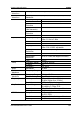
Data Type
H, L, X
Setup Time
8 ns to 1 s
Hold Time
8 ns to 1 s
RS232/UART Trigger (Optional)
Polarity
Normal, Invert
Trigger Condition
Start, Error, Check Error, Data
Baud Rate
2400 bps, 4800 bps, 9600 bps, 19200 bps, 38400 bps, 57600
bps, 115200 bps, 230400 bps, 460800 bps, 921600 bps, 1
Mbps and User
Data Bits
5 bit, 6 bit, 7 bit, 8 bit
I2C Trigger (Optional)
Trigger Condition
Start, Restart, Stop, Missing ACK, Address, Data, A&D
Address Bits
7 bits, 8 bits, 10 bits
Address Range
0 to 127, 0 to 255, 0 to 1023
Byte Length
1 to 5
SPI Trigger (Optional)
Trigger Condition
Timeout, CS
Timeout Value
16 ns to 10 s
Data Bits
4 bit to 32 bit
Data Line Setting
H, L, X
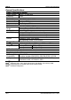
Measure
Cursor
Manual Mode
Voltage Deviation between Cursors (△V)
Time Deviation between Cursors (
△
T)
Reciprocal of
△
T (Hz) (1/
△
T)
Track Mode
Voltage and Time Values of the Waveform
Point
Auto Mode
Allow to display cursors during auto
measurement
Auto
Measurement
Analog channel:
Period, Frequency, Rise Time, Fall Time, Positive Pulse Width,
Negative Pulse Width, Positive Duty Cycle, Negative Duty
Cycle, Positive Pulse Count, Negative Pulse Count, Rising Edge
Count, Falling Edge Count, tVmax, tVmin, Positive Rate,
Negative Rate, Delay
12, Delay 12, Phase 12,
Phase
12, Maximum, Minimum, Peak-Peak Value, Top
Value, Bottom Value, Amplitude, Upper Value, Middle Value,
Lower Value, Average, Vrms, Overshoot, Pre-shoot, Area,
Period Area, Period Vrms, Variance
Digital channel:
Period, Frequency, Positive Pulse Width, Negative Pulse Width,
Positive Duty Cycle, Negative Duty Cycle, Delay
12, Delay
12, Phase 12, Phase 12