
User manual


Chapter 5 To Trigger the Oscilloscope RIGOL
MSO2000A/DS2000A User’s Guide 5-3
Trigger Mode
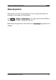
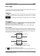
The following is the schematic diagram of the acquisition memory. To easily
understand the trigger event, the acquisition memory is divided into the pre-trigger
buffer and post-trigger buffer.
Figure 5-1 Schematic Diagram of the Acquisition Memory
After the system runs, the oscilloscope operates by first filling the pre-trigger buffer.
It starts searching for a trigger after the pre-trigger buffer is filled. While searching
for the trigger, the data sampled will still be transmitted to the pre-trigger buffer (the
new data will continuously overwrite the previous date). When a trigger is found, the
pre-trigger buffer contains the data acquired just before the trigger. Then, the
oscilloscope will fill the post-trigger buffer and display the data in the acquisition
memory. If the acquisition is activated via RUN/STOP, the oscilloscope will repeat
this process; if the acquisition is activated via SINGLE, the oscilloscope will stop
after finishing a single acquisition (you can pan and zoom the waveform currently
displayed).
Press MODE in the trigger control area (TRIGGER) at the front panel or press
MENU Sweep to select the desired trigger mode. The corresponding status light
of the mode currently selected turns on.
Auto:
In this trigger mode, the oscilloscope will trigger, sample and display waveform
forcibly if no specified trigger condition is found.
This trigger mode should be used when the signal level is unknown or the DC should
be displayed as well as when forcible trigger is not necessary as the trigger condition
always occurs.
Pre-trigger Buffer
Post-trigger Buffer
Trigger Event
Acquisition memory