
Data Sheet


RIGOL 6 To Make Measurements
MSO4000/DS4000 User’s Guide
6-28
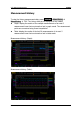
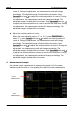
CurA: the X value at cursor A. X value takes the trigger position as reference.
D15D0: display the logic level value of the current cursor A with hex and binary
data which correspond to D15-D0 from left to right. If the current digital channel
is turned off, the channel is represented by X.
CurB: the X value at cursor B. X value takes the trigger position as reference.
D15D0: display the logic level value of the current cursor B with hex and binary
data which correspond to D15-D0 from left to right. If the current digital channel
is turned off, the channel is represented by X.
If needed, please refer to the following steps to modify the parameters of manual
cursor measurement.
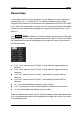
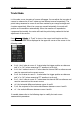
1. Select Display Mode
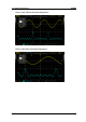
Press DisplayMode to select “X”, “Y” or “X-Y”. The X cursors are a pair of
vertical solid/dotted lines and are usually used to measure the time parameters.
The Y cursors are a pair of horizontal solid/dotted lines and are usually used to
measure the voltage parameters. The X-Y cursors are a pair of vertical and
horizontal solid/dotted lines and can be used to measure the time and voltage
parameters at the same time.
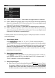
2. Select Measurement Source
Press Source to select the waveform of the analog channels (CH1 to CH4) or
math operation results (MATH) or the digital channel (LA) for measurement. If
“None” is selected, no cursor will be displayed.
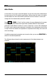
3. Select Screen Region
When Zoom is turned on (pressing Horizontal
SCALE can turn on Zoom),
the screen is divided into the Main and Zoom areas. Press Screen Region
to select Main or Zoom. When Main is selected, the cursors are displayed in
the Main area and are used to measure the parameters in the Main are; the