
Data Sheet


RIGOL 8 Protocol Decoding
MSO4000/DS4000 User’s Guide
8-2
Parallel Decoding
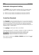
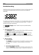
Parallel bus consists of a clock line and data lines. As shown in the figure below, CLK
is the clock line, while Bit0 and Bit1 are the 0 bit and 1st bit on the data line
respectively.
Bit0
Bit1
CLK
The oscilloscope will sample the channel data on the rising edge, falling edge or the
rising&falling edges of the clock and judge each data point (logic “1” or logic “0”)
according to the preset threshold level.
Press Decode1 Decode to select “Parallel” and open the parallel decoding
function menu.
1. Clock Line Setting (CLK)
Press CLKChannel to select any channel (CH1 to CH4 or D0-D15) as the clock
channel. If “None” is selected, no clock channel is set.
Press Slope to set the oscilloscope to sample the channel data on the rising
edge (
), falling edge ( ) or rising&falling edges ( ). If no clock
channel is selected, the instrument will sample when the channel data jumps in
the decoding.
2. Data Line Setting
Set the bus bits
Press Bus Bits to set the data width of the parallel bus namely the number
of bits per frame. The default is 1 and the maximum is 20 bits (Bit0,
Bit…Bit19).
Specify data channel for each bit.
First, press CurrentBit to select the bit that needs to specify channel. The
default is 0 and the range available is always 1 smaller than the bus bits. For