
Data Sheet

2 To Set the Vertical System RIGOL
MSO4000/DS4000 User’s Guide
2-3
Channel Coupling
Set the coupling mode to filter out the undesired signals. For example, the signal
under test is a square waveform with DC offset.
When the coupling mode is “DC”: the DC and AC components of the signal under
test can both pass the channel.
When the coupling mode is “AC”: the DC components of the signal under test
are blocked.
When the coupling mode is “GND”: the DC and AC components of the signal
under test are both blocked.
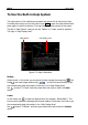
Press CH1 Coupling and use to select the desired coupling mode (the
default is DC). The current coupling mode is displayed in the channel label at the
bottom of the screen. When “AC” is selected, the character “AC” below CH1 at the
front panel will be illuminated. You can also press Coupling continuously to switch
the coupling mode.