
Data Sheet

5 To Trigger the Oscilloscope RIGOL
MSO4000D/S4000 User’s Guide
5-3
Trigger Mode
The trigger mode affects the way in which the oscilloscope searches for the trigger.
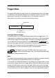
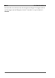
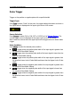
The following is the schematic diagram of the acquisition memory. As shown in the
figure below, the position of the trigger event in the acquisition memory is
determined by the reference time point and the delay setting.
Pre-trigger/Delayed trigger:
This area is where you can view data acquired before/after the trigger event. The
trigger position is usually at the horizontal center of the screen. In full-screen display,
seven-grid pre-trigger and delayed trigger information are displayed respectively.
You can adjust the horizontal position through HORIZONTAL
POSITION to
view more pre-trigger information, through which the signal information before/after
the trigger (such as capture the glitch generated by the circuit and analyze the
pre-trigger data to find out the reasons for glitch) can be obtained.
Press MODE in the trigger control area (TRIGGER) at the front panel or press
MENU Sweep to select the desired trigger mode. The corresponding status light
of the mode currently selected turns on.
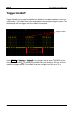
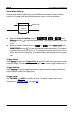
Auto:
This trigger mode automatically triggers regardless of whether the trigger condition
is met. A horizontal line is displayed when there is no input signal.
In this mode, the oscilloscope operates by first filling the pre-trigger buffer. It starts
searching for a trigger after the pre-trigger buffer is filled and continues to flow data
through this buffer while it searches for the trigger. While searching for the trigger,
the oscilloscope overflows the pre-trigger buffer and the first data put into the buffer
is first pushed out (FIFO). When a trigger is found, the pre-trigger buffer contains
Pre-trigger Buffer Post-trigger Buffer
Trigger Event
Acquisition memory