
Data Sheet

1 Quick Start RIGOL
MSO4000/DS4000 User’s Guide
1-25
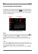
2. Analog Channel Label/Waveform
Each analog channel is color coded to match the input. For example, CH1 is
yellow and CH2 is light blue.
3. Digital Channel Label/Waveform
The logic high levels of the digital waveforms are displayed in blue, the logic
low levels are displayed in green which complies with the color of the digital
channel label and the edges are displayed in white. Both the label and the
waveform of the digital channel currently selected are displayed in red.
4. Status
Available states include RUN, STOP, T’D (triggered), WAIT and AUTO.
5. Horizontal Time Base
Represent the time per grid on the horizontal axis on the screen.
Use HORIZONTAL
SCALE to modify this parameter. The range
available is from 1.000 ns to 1000 s.
6. Sample Rate/Memory Depth
Displays the current sample rate and memory depth of the oscilloscope.
Use HORIZONTAL
SCALE to modify this parameter.
7. Waveform Memory
Provides the schematic diagram of the memory position of the waveform
currently on the screen.
8. Trigger Position
Displays the trigger position of the waveform.
9. Horizontal Position
Use HORIZONTAL
POSITION to modify this parameter. Press down
the knob to automatically set the parameter to 0.
waveform on the
screen