
Data Sheet

1 Quick Start RIGOL
MSO4000/DS4000 User’s Guide
1-27
setting: Channel Coupling (such as in AC coupling), Bandwidth
Limit (such as when bandwidth limit is enabled) and Input
Impedance (such as when the input impedance is 50 Ω).
15. CH3 Vertical Scale
Displays the voltage value per grid of the CH3 waveform.
Use VIRTICAL
SCALE to modify this parameter.
The following labels will be provided according to the current channel
setting:
Channel Coupling (such as in AC coupling), Bandwidth
Limit (such as when bandwidth limit is enabled) and Input
Impedance (such as when the input impedance is 50 Ω).
16. CH4 Vertical Scale
Displays the voltage value per grid of the CH4 waveform.
Use VIRTICAL
SCALE to modify this parameter.
The following labels will be provided according to the current channel
setting:
Channel Coupling (such as in AC coupling), Bandwidth
Limit (such as when bandwidth limit is enabled) and iInput
Impedance (such as when the input impedance is 50 Ω).
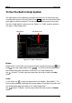
17. Message Box
Displays prompt messages.
18. Digital Channel Status Area
Displays the current state of the 16 digital channels (D0 to D15 from right to
left). The digital channels currently enabled are displayed in green and the
digital channel currently selected is highlighted in red. Any digital channel
that is turned off will be grayed out in the Digital Channel Status Area.
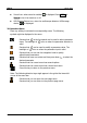
19. Notification Area
Displays system time, sound icon and USB storage device icon.
System Time: displayed in “hh:mm (hour:minute)” format. When
printing or storing the waveform, the output file will contain this time
message. Press Utility System System Time to set the time in
the following format:
yyyy-mm-dd hh:mm:ss
(year-month-date hour:minute:second)