
Instructions
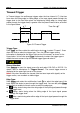

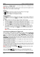


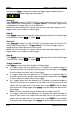
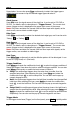
Table Of Contents
- Guaranty and Declaration
- Safety Requirement
- MSO5000-E Series Overview
- Document Overview
- Quick Start
- General Inspection
- Appearance and Dimensions
- To Prepare for Use
- Front Panel Overview
- Rear Panel Overview
- Front Panel Function Overview
- User Interface
- Touch Screen Controls
- Parameter Setting Method
- To Use the Kensington Security Lock
- To Use the Built-in Help System
- To View the Option Information and the Option Installation
- To Set the Vertical System
- To Set the Horizontal System
- To Set the Sample System
- To Trigger the Oscilloscope
- Trigger Source
- Trigger LEVEL/Threshold Level
- Trigger Mode
- Trigger Coupling
- Trigger Holdoff
- Noise Rejection
- Trigger Type
- Edge Trigger
- Pulse Trigger
- Slope Trigger
- Video Trigger
- Pattern Trigger
- Duration Trigger
- Timeout Trigger
- Runt Trigger
- Window Trigger
- Delay Trigger
- Setup/Hold Trigger
- Nth Edge Trigger
- RS232 Trigger (Option)
- I2C Trigger (Option)
- SPI Trigger (Option)
- CAN Trigger (Option)
- FlexRay Trigger (Option)
- LIN Trigger (Option)
- I2S Trigger (Option)
- MIL-STD-1553 Trigger (Option)
- Zone Trigger
- Trigger Output Connector
- Operations and Measurements
- Digital Voltmeter (DVM) and Frequency Counter
- Power Analysis (Option)
- Histogram Analysis
- Digital Channel
- Protocol Decoding
- Reference Waveform
- To Enable Ref Function
- To Select the Reference Channel
- To Select the Ref Source
- To Adjust the Ref Waveform Display
- To Save to Internal Memory
- To Clear the Display of the Reference Waveform
- To View Details of the Reference Waveform
- To Reset the Reference Waveform
- Color Setting
- Label Setting
- To Export to Internal or External Memory
- To Import from Internal or External Memory
- Pass/Fail Test
- Waveform Recording & Playing
- Search and Navigation Function
- Display Control
- Function/Arbitrary Waveform Generator (Option)
- Store and Load
- System Utility Function Setting
- Remote Control
- Troubleshooting
- Appendix
- Index
Chapter 5 To Trigger the Oscilloscope RIGOL
MSO5000-E User Guide 5-25
and they move up and down with the change of the trigger level. At the same time,
the real-time trigger level information is displayed at the lower-left corner of the
screen (as shown in the figure below, H indicates the upper limit of the trigger level,
L indicates the lower limit of the trigger level, and △ indicates the trigger level
deviation). When you stopping modifying the trigger level, the trigger level line and
the trigger level information at the lower-left corner of the screen disappear in about
2 s. The current trigger level deviation is displayed at the upper-right corner of the
screen.
Trigger Mode:
In the trigger control area (Trigger) on the front panel, press Mode to quickly switch
the current trigger mode. For details, refer to descriptions in "Trigger Mode".
Trigger Parameter Setting:
Set the trigger parameters (trigger holdoff and noise rejection) under this trigger
type. For details, refer to descriptions in "Trigger Holdoff" and "Noise
Rejection".
Window Trigger
Window trigger provides a high trigger level and a low trigger level. The instrument
triggers when the input signal passes through the high trigger level or the low trigger
level.
Trigger Type:
Press Type, and then rotate the multifunction knob to select "Window". Press
down the knob to select the trigger type. Then, the current trigger setting
information is displayed at the upper-right corner of the screen, as shown in the
figure below. You can also press Type continuously to select the trigger type or
enable the touch screen to tap the desired trigger type and select it.
Source Selection:
Press Source to switch the trigger source and select CH1-CH2. For details, refer to
descriptions in "
Trigger Source". The current trigger source is displayed at the
upper-right corner of the screen.
Note: Only when we select the channel (that has been input with signals) as the
trigger source, can we obtain a stable trigger.