
Instructions

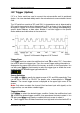
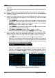
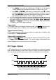


Table Of Contents
- Guaranty and Declaration
- Safety Requirement
- MSO5000-E Series Overview
- Document Overview
- Quick Start
- General Inspection
- Appearance and Dimensions
- To Prepare for Use
- Front Panel Overview
- Rear Panel Overview
- Front Panel Function Overview
- User Interface
- Touch Screen Controls
- Parameter Setting Method
- To Use the Kensington Security Lock
- To Use the Built-in Help System
- To View the Option Information and the Option Installation
- To Set the Vertical System
- To Set the Horizontal System
- To Set the Sample System
- To Trigger the Oscilloscope
- Trigger Source
- Trigger LEVEL/Threshold Level
- Trigger Mode
- Trigger Coupling
- Trigger Holdoff
- Noise Rejection
- Trigger Type
- Edge Trigger
- Pulse Trigger
- Slope Trigger
- Video Trigger
- Pattern Trigger
- Duration Trigger
- Timeout Trigger
- Runt Trigger
- Window Trigger
- Delay Trigger
- Setup/Hold Trigger
- Nth Edge Trigger
- RS232 Trigger (Option)
- I2C Trigger (Option)
- SPI Trigger (Option)
- CAN Trigger (Option)
- FlexRay Trigger (Option)
- LIN Trigger (Option)
- I2S Trigger (Option)
- MIL-STD-1553 Trigger (Option)
- Zone Trigger
- Trigger Output Connector
- Operations and Measurements
- Digital Voltmeter (DVM) and Frequency Counter
- Power Analysis (Option)
- Histogram Analysis
- Digital Channel
- Protocol Decoding
- Reference Waveform
- To Enable Ref Function
- To Select the Reference Channel
- To Select the Ref Source
- To Adjust the Ref Waveform Display
- To Save to Internal Memory
- To Clear the Display of the Reference Waveform
- To View Details of the Reference Waveform
- To Reset the Reference Waveform
- Color Setting
- Label Setting
- To Export to Internal or External Memory
- To Import from Internal or External Memory
- Pass/Fail Test
- Waveform Recording & Playing
- Search and Navigation Function
- Display Control
- Function/Arbitrary Waveform Generator (Option)
- Store and Load
- System Utility Function Setting
- Remote Control
- Troubleshooting
- Appendix
- Index
Chapter 5 To Trigger the Oscilloscope RIGOL
MSO5000-E User Guide 5-37
Press Bytes, then rotate the multifunction knob or use the pop-up
numeric keypad to set the length of the data. Its range is from 1 to 5.
Press More Addr Bits, and rotate the multifunction knob to select
the desired address bits. Then press down the knob to select it. You can
also press Addr Bits continuously or enable the touch screen to select it.
The available address bits are "7 Bits", "8 Bits", and "10 Bits".
A & D: the oscilloscope searches for the specified address and data at the same
time, then triggers when both the address and data meet the conditions. After
this trigger condition is selected, you need to set Bit X, Bytes, Addr Bits,
Address, and Direction menu items. For setting methods, refer to descriptions
in "Address" and "Data" trigger conditions.
Trigger Mode:
In the trigger control area (Trigger) on the front panel, press Mode to quickly switch
the current trigger mode. For details, refer to descriptions in "Trigger Mode".
Trigger Parameter Setting:
Set the trigger parameter (noise rejection) under this trigger type. For details, refer
to descriptions in "Noise Rejection".
Trigger LEVEL/Threshold Level:
Rotate the Trigger
LEVEL knob to adjust the trigger level/threshold level. Refer
to "
Trigger LEVEL/Threshold Level". The current trigger level/threshold level
value is displayed at the upper-right corner of the screen.
SPI Trigger (Option)
In SPI trigger, after the CS or timeout condition is satisfied, the oscilloscope triggers
when the specified data is found. When using SPI trigger, you need to specify the
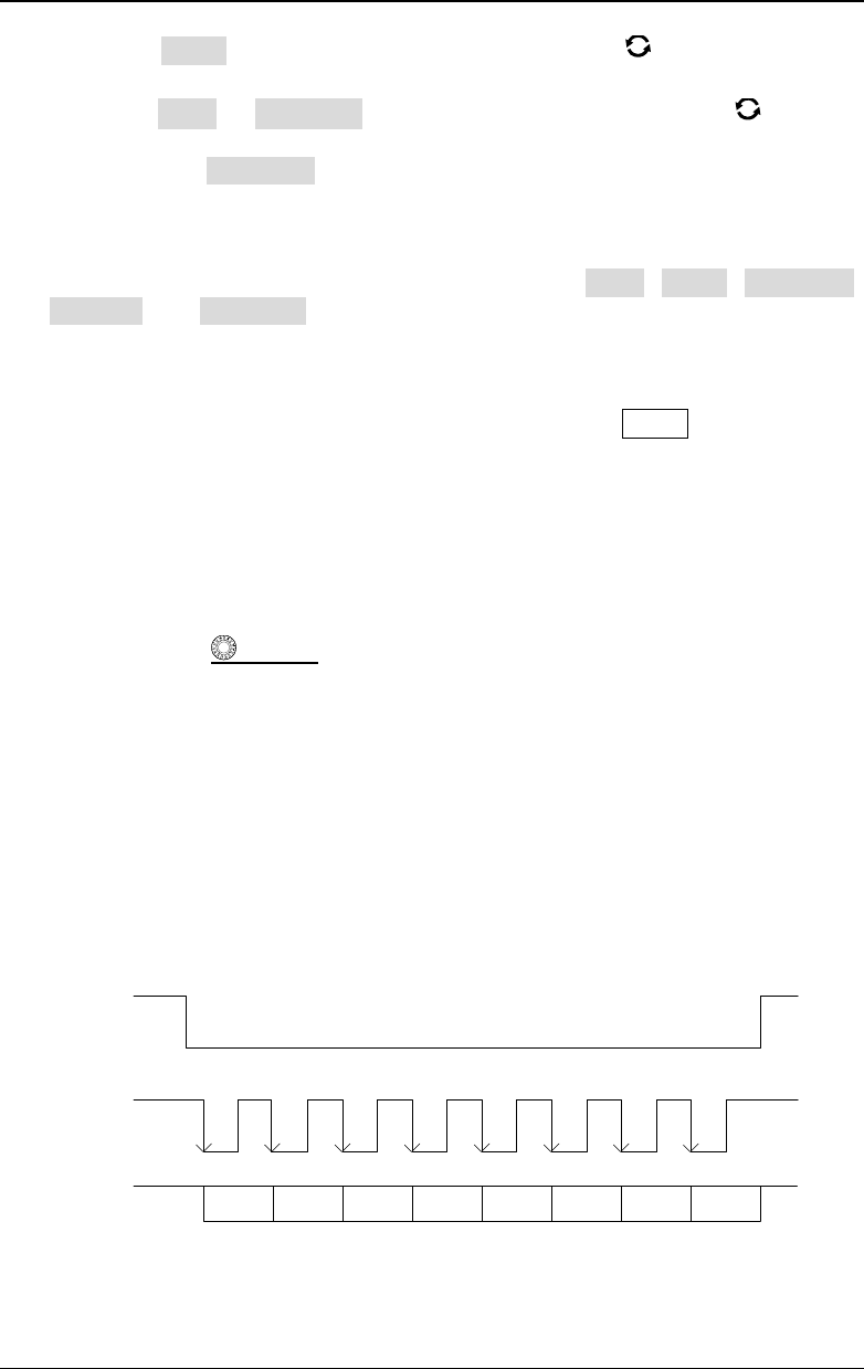
SCL clock sources and SDA data sources. Below is the sequential chart of SPI bus.
SDA
SCL
CS
D7 D
6 D5 D4
D3 D2
D1 D0
Figure 5-16 Sequential Chart of SPI Bus