
Instructions


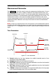


Table Of Contents
- Guaranty and Declaration
- Safety Requirement
- MSO5000-E Series Overview
- Document Overview
- Quick Start
- General Inspection
- Appearance and Dimensions
- To Prepare for Use
- Front Panel Overview
- Rear Panel Overview
- Front Panel Function Overview
- User Interface
- Touch Screen Controls
- Parameter Setting Method
- To Use the Kensington Security Lock
- To Use the Built-in Help System
- To View the Option Information and the Option Installation
- To Set the Vertical System
- To Set the Horizontal System
- To Set the Sample System
- To Trigger the Oscilloscope
- Trigger Source
- Trigger LEVEL/Threshold Level
- Trigger Mode
- Trigger Coupling
- Trigger Holdoff
- Noise Rejection
- Trigger Type
- Edge Trigger
- Pulse Trigger
- Slope Trigger
- Video Trigger
- Pattern Trigger
- Duration Trigger
- Timeout Trigger
- Runt Trigger
- Window Trigger
- Delay Trigger
- Setup/Hold Trigger
- Nth Edge Trigger
- RS232 Trigger (Option)
- I2C Trigger (Option)
- SPI Trigger (Option)
- CAN Trigger (Option)
- FlexRay Trigger (Option)
- LIN Trigger (Option)
- I2S Trigger (Option)
- MIL-STD-1553 Trigger (Option)
- Zone Trigger
- Trigger Output Connector
- Operations and Measurements
- Digital Voltmeter (DVM) and Frequency Counter
- Power Analysis (Option)
- Histogram Analysis
- Digital Channel
- Protocol Decoding
- Reference Waveform
- To Enable Ref Function
- To Select the Reference Channel
- To Select the Ref Source
- To Adjust the Ref Waveform Display
- To Save to Internal Memory
- To Clear the Display of the Reference Waveform
- To View Details of the Reference Waveform
- To Reset the Reference Waveform
- Color Setting
- Label Setting
- To Export to Internal or External Memory
- To Import from Internal or External Memory
- Pass/Fail Test
- Waveform Recording & Playing
- Search and Navigation Function
- Display Control
- Function/Arbitrary Waveform Generator (Option)
- Store and Load
- System Utility Function Setting
- Remote Control
- Troubleshooting
- Appendix
- Index
Chapter 6 Operations and Measurements RIGOL
MSO5000-E User Guide 6-29
Measurement Parameter
Press Measure on the front panel to enter the measurement setting menu. You can
set the measurement source, enable or disable the all measurement function, the
statistical analysis function, and etc. You can also quickly make measurements for 41
waveform parameters. The measurement results will be displayed on the screen. The
measurement results on the screen are always marked in the same color as the
current measurement channel. You can also enable the touch screen to tap the auto
measurement label "Measure" at the top of the screen to enter the measurement
setting menu.
Note: If there is no signal input for the current source or the measurement result is
not within the valid range (too large or too small), then the measurement results are
invalid, and "*****" is displayed on the screen. Please re-input the signal or set the
signal.
Time Parameters
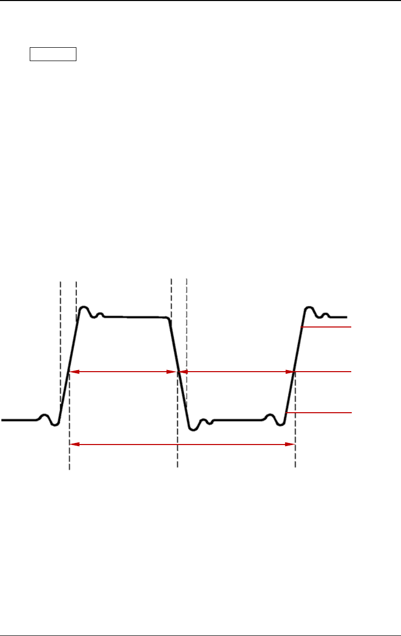
Figure 6-1 Time Parameters
1. Period: defined as the time between the middle threshold points of two
consecutive, like-polarity edges.
2. Frequency: defined as the reciprocal of period.
3. Rise Time: indicates the time for the signal amplitude to rise from the threshold
lower limit to the threshold upper limit.
4. Fall Time: indicates the time for the signal amplitude to rise from the threshold
upper limit to the threshold lower limit.
5. +Width: indicates the time between the threshold middle value of a rising edge
to the threshold middle value of the next falling edge.
Fall Time
Threshold
Upper Limit
Threshold
Middle Value
Threshold
Lower Limit
+Width
-Width
Period
Rise Time