
Instructions


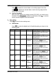

Table Of Contents
- Guaranty and Declaration
- Safety Requirement
- MSO5000-E Series Overview
- Document Overview
- Quick Start
- General Inspection
- Appearance and Dimensions
- To Prepare for Use
- Front Panel Overview
- Rear Panel Overview
- Front Panel Function Overview
- User Interface
- Touch Screen Controls
- Parameter Setting Method
- To Use the Kensington Security Lock
- To Use the Built-in Help System
- To View the Option Information and the Option Installation
- To Set the Vertical System
- To Set the Horizontal System
- To Set the Sample System
- To Trigger the Oscilloscope
- Trigger Source
- Trigger LEVEL/Threshold Level
- Trigger Mode
- Trigger Coupling
- Trigger Holdoff
- Noise Rejection
- Trigger Type
- Edge Trigger
- Pulse Trigger
- Slope Trigger
- Video Trigger
- Pattern Trigger
- Duration Trigger
- Timeout Trigger
- Runt Trigger
- Window Trigger
- Delay Trigger
- Setup/Hold Trigger
- Nth Edge Trigger
- RS232 Trigger (Option)
- I2C Trigger (Option)
- SPI Trigger (Option)
- CAN Trigger (Option)
- FlexRay Trigger (Option)
- LIN Trigger (Option)
- I2S Trigger (Option)
- MIL-STD-1553 Trigger (Option)
- Zone Trigger
- Trigger Output Connector
- Operations and Measurements
- Digital Voltmeter (DVM) and Frequency Counter
- Power Analysis (Option)
- Histogram Analysis
- Digital Channel
- Protocol Decoding
- Reference Waveform
- To Enable Ref Function
- To Select the Reference Channel
- To Select the Ref Source
- To Adjust the Ref Waveform Display
- To Save to Internal Memory
- To Clear the Display of the Reference Waveform
- To View Details of the Reference Waveform
- To Reset the Reference Waveform
- Color Setting
- Label Setting
- To Export to Internal or External Memory
- To Import from Internal or External Memory
- Pass/Fail Test
- Waveform Recording & Playing
- Search and Navigation Function
- Display Control
- Function/Arbitrary Waveform Generator (Option)
- Store and Load
- System Utility Function Setting
- Remote Control
- Troubleshooting
- Appendix
- Index
RIGOL Chapter 10 Digital Channel
10-4 MSO5000-E User Guide
at the right side of the threshold field, and then the threshold selection list is
displayed. Tap to select the preset threshold. Or tap the threshold input field and
input the value with the pop-up numeric keypad.
Probe Calibration
When the probe is connected to the oscilloscope for the first time or the
temperature change is more than 5 degrees, you are recommended to calibrate
the probe zero using the calibration function. Please disconnect all the
connections to the PLA2216 input terminal during the calibration.
Press Threshold Calibration to calibrate the probe zero automatically. After the
calibration is completed, the interface will pop up a dialog box to remind the
calibration result.
Auto Arrangement Setting
Press Arrange to select the waveform arrangement order of the currently enabled
channels on the screen. You can select "D0-D15" or "D15-D0", and the default is
"D0-D15".
D0-D15: the waveforms on the screen are D0-D15 in sequence from top to
bottom.
D15-D0: the waveforms on the screen are D15-D0 in sequence from top to
bottom.
To Set the Waveform Display Size
Press Size, and rotate the multifunction knob to set the waveform display size.
Press down the knob to select it. You can also press Size continuously or enable the
touch screen to select it. The available display sizes are Small, Medium, and Large.
Note: "Large" is only available when the number of currently enabled channels is
less than or equal to 8.
To Set the Label
By default, the instrument takes D0-D15 as the channel label of the 16 digital
channels. You can set a user-defined label for each digital channel to easily
differentiate the digital channels. You can use the preset label or input a label
manually. Press Label to enter the label setting menu.