
Instructions
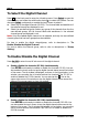


Table Of Contents
- Guaranty and Declaration
- Safety Requirement
- MSO5000-E Series Overview
- Document Overview
- Quick Start
- General Inspection
- Appearance and Dimensions
- To Prepare for Use
- Front Panel Overview
- Rear Panel Overview
- Front Panel Function Overview
- User Interface
- Touch Screen Controls
- Parameter Setting Method
- To Use the Kensington Security Lock
- To Use the Built-in Help System
- To View the Option Information and the Option Installation
- To Set the Vertical System
- To Set the Horizontal System
- To Set the Sample System
- To Trigger the Oscilloscope
- Trigger Source
- Trigger LEVEL/Threshold Level
- Trigger Mode
- Trigger Coupling
- Trigger Holdoff
- Noise Rejection
- Trigger Type
- Edge Trigger
- Pulse Trigger
- Slope Trigger
- Video Trigger
- Pattern Trigger
- Duration Trigger
- Timeout Trigger
- Runt Trigger
- Window Trigger
- Delay Trigger
- Setup/Hold Trigger
- Nth Edge Trigger
- RS232 Trigger (Option)
- I2C Trigger (Option)
- SPI Trigger (Option)
- CAN Trigger (Option)
- FlexRay Trigger (Option)
- LIN Trigger (Option)
- I2S Trigger (Option)
- MIL-STD-1553 Trigger (Option)
- Zone Trigger
- Trigger Output Connector
- Operations and Measurements
- Digital Voltmeter (DVM) and Frequency Counter
- Power Analysis (Option)
- Histogram Analysis
- Digital Channel
- Protocol Decoding
- Reference Waveform
- To Enable Ref Function
- To Select the Reference Channel
- To Select the Ref Source
- To Adjust the Ref Waveform Display
- To Save to Internal Memory
- To Clear the Display of the Reference Waveform
- To View Details of the Reference Waveform
- To Reset the Reference Waveform
- Color Setting
- Label Setting
- To Export to Internal or External Memory
- To Import from Internal or External Memory
- Pass/Fail Test
- Waveform Recording & Playing
- Search and Navigation Function
- Display Control
- Function/Arbitrary Waveform Generator (Option)
- Store and Load
- System Utility Function Setting
- Remote Control
- Troubleshooting
- Appendix
- Index

RIGOL Chapter 10 Digital Channel
10-6 MSO5000-E User Guide
knob to ungroup the channels.
Note:
You can only ungroup the digital channels.
If no group is set, the Ungroup menu and the Group On/Off menu are
grayed out and disabled.
Waveform Color of the Digital Channel
When the digital channel is enabled, its corresponding waveforms and label are
displayed on the screen. This oscilloscope supports setting high logic level display
color, low logic level display color, and edge display color.
Press More Color to enter the waveform color setting menu.
Press High, and rotate the multifunction knob to set the color of high logic
level. Press down the knob to select it. You can also press High continuously or
enable the touch screen to select it.
Press Edge, and rotate the multifunction knob to set the edge color. Press
down the knob to select it. You can also press Edge continuously or enable the
touch screen to select it.
Press Low, and rotate the multifunction knob to set the color of low logic
level. Press down the knob to select it. You can also press Low continuously or
enable the touch screen to select it.