
Instructions


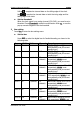

Table Of Contents
- Guaranty and Declaration
- Safety Requirement
- MSO5000-E Series Overview
- Document Overview
- Quick Start
- General Inspection
- Appearance and Dimensions
- To Prepare for Use
- Front Panel Overview
- Rear Panel Overview
- Front Panel Function Overview
- User Interface
- Touch Screen Controls
- Parameter Setting Method
- To Use the Kensington Security Lock
- To Use the Built-in Help System
- To View the Option Information and the Option Installation
- To Set the Vertical System
- To Set the Horizontal System
- To Set the Sample System
- To Trigger the Oscilloscope
- Trigger Source
- Trigger LEVEL/Threshold Level
- Trigger Mode
- Trigger Coupling
- Trigger Holdoff
- Noise Rejection
- Trigger Type
- Edge Trigger
- Pulse Trigger
- Slope Trigger
- Video Trigger
- Pattern Trigger
- Duration Trigger
- Timeout Trigger
- Runt Trigger
- Window Trigger
- Delay Trigger
- Setup/Hold Trigger
- Nth Edge Trigger
- RS232 Trigger (Option)
- I2C Trigger (Option)
- SPI Trigger (Option)
- CAN Trigger (Option)
- FlexRay Trigger (Option)
- LIN Trigger (Option)
- I2S Trigger (Option)
- MIL-STD-1553 Trigger (Option)
- Zone Trigger
- Trigger Output Connector
- Operations and Measurements
- Digital Voltmeter (DVM) and Frequency Counter
- Power Analysis (Option)
- Histogram Analysis
- Digital Channel
- Protocol Decoding
- Reference Waveform
- To Enable Ref Function
- To Select the Reference Channel
- To Select the Ref Source
- To Adjust the Ref Waveform Display
- To Save to Internal Memory
- To Clear the Display of the Reference Waveform
- To View Details of the Reference Waveform
- To Reset the Reference Waveform
- Color Setting
- Label Setting
- To Export to Internal or External Memory
- To Import from Internal or External Memory
- Pass/Fail Test
- Waveform Recording & Playing
- Search and Navigation Function
- Display Control
- Function/Arbitrary Waveform Generator (Option)
- Store and Load
- System Utility Function Setting
- Remote Control
- Troubleshooting
- Appendix
- Index
RIGOL Chapter 11 Protocol Decoding
11-2 MSO5000-E User Guide
Parallel Decoding
Parallel bus consists of clock line and data line. As shown in the figure below, CLK is
the clock line, whereas Bit0 and Bit1 are the 0 bit and 1st bit on the data line
respectively. The oscilloscope will sample the channel data on the rising edge, falling
edge, or the rising/falling edge of the clock and judge each data point (logic "1" or
logic "0") according to the preset threshold level.
Figure 11-1 Schematic Diagram of Parallel Decoding
In the decode setting menu, press Decode1 Bus Type, then rotate the
multifunction knob
to select "Parallel". Press down the knob to select it.
You can also press Bus Type continuously or enable the touch screen to select it.
1. Enable or disable the bus
Press Bus Status to enable or disable the decoding function.
2. Clock setting (CLK)
Press Clock to enter the clock line setting menu.
Set clock channel
Press CLK, then rotate the multifunction knob to select any clock
channel. Press down the knob to select it. You can also press CLK
continuously or enable the touch screen to select it. The analog channel
(CH1-CH2) and digital channel (D0-D15) can all be selected as the clock
source. If "OFF" is selected, no clock channel is set, and sampling is
performed when a hop occurs to the data of the data channel during
decoding.
Set the clock edge type
Press CLK Edge, then rotate the multifunction knob to select the clock
edge type. Press down the knob to select it. You can also press CLK Edge
continuously or enable the touch screen to select it. You can select to
sample the channel data on the rising edge (
), falling edge ( ), or
both edges (
) of the clock signal.
Rising
: samples the channel data on the rising edge of the clock.