
Instructions


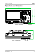
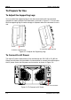
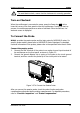

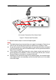
Table Of Contents
- Guaranty and Declaration
- Safety Requirement
- MSO5000-E Series Overview
- Document Overview
- Quick Start
- General Inspection
- Appearance and Dimensions
- To Prepare for Use
- Front Panel Overview
- Rear Panel Overview
- Front Panel Function Overview
- User Interface
- Touch Screen Controls
- Parameter Setting Method
- To Use the Kensington Security Lock
- To Use the Built-in Help System
- To View the Option Information and the Option Installation
- To Set the Vertical System
- To Set the Horizontal System
- To Set the Sample System
- To Trigger the Oscilloscope
- Trigger Source
- Trigger LEVEL/Threshold Level
- Trigger Mode
- Trigger Coupling
- Trigger Holdoff
- Noise Rejection
- Trigger Type
- Edge Trigger
- Pulse Trigger
- Slope Trigger
- Video Trigger
- Pattern Trigger
- Duration Trigger
- Timeout Trigger
- Runt Trigger
- Window Trigger
- Delay Trigger
- Setup/Hold Trigger
- Nth Edge Trigger
- RS232 Trigger (Option)
- I2C Trigger (Option)
- SPI Trigger (Option)
- CAN Trigger (Option)
- FlexRay Trigger (Option)
- LIN Trigger (Option)
- I2S Trigger (Option)
- MIL-STD-1553 Trigger (Option)
- Zone Trigger
- Trigger Output Connector
- Operations and Measurements
- Digital Voltmeter (DVM) and Frequency Counter
- Power Analysis (Option)
- Histogram Analysis
- Digital Channel
- Protocol Decoding
- Reference Waveform
- To Enable Ref Function
- To Select the Reference Channel
- To Select the Ref Source
- To Adjust the Ref Waveform Display
- To Save to Internal Memory
- To Clear the Display of the Reference Waveform
- To View Details of the Reference Waveform
- To Reset the Reference Waveform
- Color Setting
- Label Setting
- To Export to Internal or External Memory
- To Import from Internal or External Memory
- Pass/Fail Test
- Waveform Recording & Playing
- Search and Navigation Function
- Display Control
- Function/Arbitrary Waveform Generator (Option)
- Store and Load
- System Utility Function Setting
- Remote Control
- Troubleshooting
- Appendix
- Index
Chapter 1 Quick Start RIGOL
MSO5000-E User Guide 1-5
CAUTION
To avoid electric shock, ensure that the instrument is correctly grounded.
Turn-on Checkout
When the oscilloscope is connected to power, press the Power key
at the
lower-left corner of the front panel to start the oscilloscope. During the start-up
process, the oscilloscope performs a series of self-tests. After the self-test, the
welcome screen is displayed.
To Connect the Probe
RIGOL provides the passive probe and the logic probe for MSO5000-E series. For
specific probe models, please refer to
MSO5000-E Series Datasheet
. For detailed
technical information of the probes, please refer to the specified Probe User’s Guide.
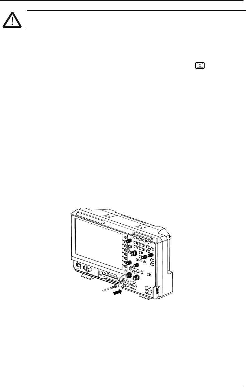
Connect the passive probe:
1. Connect the BNC terminal of the probe to an analog channel input terminal of
the oscilloscope on the front panel, as shown in Figure 1-5.
2. Connect the ground alligator clip or spring of the probe to the circuit ground
terminal, and then connect the probe tip to the circuit point to be tested.
Figure 1-5 To Connect the Passive Probe
After you connect the passive probe, check the probe function and probe
compensation adjustment before making measurements. For detailed procedures,
refer to "Function Inspection" and "Probe Compensation".