
Instructions
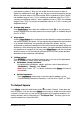


Table Of Contents
- Guaranty and Declaration
- Safety Requirement
- MSO5000-E Series Overview
- Document Overview
- Quick Start
- General Inspection
- Appearance and Dimensions
- To Prepare for Use
- Front Panel Overview
- Rear Panel Overview
- Front Panel Function Overview
- User Interface
- Touch Screen Controls
- Parameter Setting Method
- To Use the Kensington Security Lock
- To Use the Built-in Help System
- To View the Option Information and the Option Installation
- To Set the Vertical System
- To Set the Horizontal System
- To Set the Sample System
- To Trigger the Oscilloscope
- Trigger Source
- Trigger LEVEL/Threshold Level
- Trigger Mode
- Trigger Coupling
- Trigger Holdoff
- Noise Rejection
- Trigger Type
- Edge Trigger
- Pulse Trigger
- Slope Trigger
- Video Trigger
- Pattern Trigger
- Duration Trigger
- Timeout Trigger
- Runt Trigger
- Window Trigger
- Delay Trigger
- Setup/Hold Trigger
- Nth Edge Trigger
- RS232 Trigger (Option)
- I2C Trigger (Option)
- SPI Trigger (Option)
- CAN Trigger (Option)
- FlexRay Trigger (Option)
- LIN Trigger (Option)
- I2S Trigger (Option)
- MIL-STD-1553 Trigger (Option)
- Zone Trigger
- Trigger Output Connector
- Operations and Measurements
- Digital Voltmeter (DVM) and Frequency Counter
- Power Analysis (Option)
- Histogram Analysis
- Digital Channel
- Protocol Decoding
- Reference Waveform
- To Enable Ref Function
- To Select the Reference Channel
- To Select the Ref Source
- To Adjust the Ref Waveform Display
- To Save to Internal Memory
- To Clear the Display of the Reference Waveform
- To View Details of the Reference Waveform
- To Reset the Reference Waveform
- Color Setting
- Label Setting
- To Export to Internal or External Memory
- To Import from Internal or External Memory
- Pass/Fail Test
- Waveform Recording & Playing
- Search and Navigation Function
- Display Control
- Function/Arbitrary Waveform Generator (Option)
- Store and Load
- System Utility Function Setting
- Remote Control
- Troubleshooting
- Appendix
- Index

RIGOL Chapter 17 Function/Arbitrary Waveform Generator (Option)
17-12 MSO5000-E User Guide
Apply
Press Apply to apply the current settings for the currently edited arbitrary
waveforms and output the edited waveforms.
Save the arbitrary waveform
Press Save to enter the file saving interface. Please refer to descriptions in
"
Store and Load" to save the currently edited waveform file to the internal or
external memory in "*.arb" format (you can overwrite the original file or save
the currently edited waveform again).
To Edit Waveforms
You can edit the waveforms in the current volatile memory. Press Edit to enter the
waveform editing menu.
Set the frequency or period
First select Frequency or Period, then rotate the multifunction knob to
select "Frequency" or "Period". You can also press Frequency or Period
continuously to select it. Also, you can enable the touch screen to select it.
Rotate the multifunction knob
or use the pop-up numeric keypad to set the
frequency or period value of the current signal.
Set the amplitude or high level
First select Amplitude or High Level, then rotate the multifunction knob
to select "Amplitude" or "High Level". You can also press Amplitude or High
Level continuously to select it. Also, you can enable the touch screen to select it.
Rotate the multifunction knob
or use the pop-up numeric keypad to set the
amplitude or high level value of the current signal. Note that if you select
"Amplitude" for this menu, then the menu below the Amplitude is
automatically turns out to be "Offset"; if you select "High Level" for this menu,
then the menu below the High Level is automatically turns out to be "Low
Level".
Set the offset and low level
First select Offset or Low Level, then rotate the multifunction knob to
select "Offset" or "Low Level". You can also press Offset or Low Level
continuously to select it. Also, you can enable the touch screen to select it.
Rotate the multifunction knob
or use the pop-up numeric keypad to set the
offset or low level value of the current signal.
Linear Interpolation
Press Linear Interp to enable or disable the linear interpolation between the
defined points of the waveform.
ON: enables the linear interpolation. The waveform editor connects two
defined points by using a straight line.