
Instructions
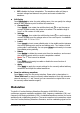


Table Of Contents
- Guaranty and Declaration
- Safety Requirement
- MSO5000-E Series Overview
- Document Overview
- Quick Start
- General Inspection
- Appearance and Dimensions
- To Prepare for Use
- Front Panel Overview
- Rear Panel Overview
- Front Panel Function Overview
- User Interface
- Touch Screen Controls
- Parameter Setting Method
- To Use the Kensington Security Lock
- To Use the Built-in Help System
- To View the Option Information and the Option Installation
- To Set the Vertical System
- To Set the Horizontal System
- To Set the Sample System
- To Trigger the Oscilloscope
- Trigger Source
- Trigger LEVEL/Threshold Level
- Trigger Mode
- Trigger Coupling
- Trigger Holdoff
- Noise Rejection
- Trigger Type
- Edge Trigger
- Pulse Trigger
- Slope Trigger
- Video Trigger
- Pattern Trigger
- Duration Trigger
- Timeout Trigger
- Runt Trigger
- Window Trigger
- Delay Trigger
- Setup/Hold Trigger
- Nth Edge Trigger
- RS232 Trigger (Option)
- I2C Trigger (Option)
- SPI Trigger (Option)
- CAN Trigger (Option)
- FlexRay Trigger (Option)
- LIN Trigger (Option)
- I2S Trigger (Option)
- MIL-STD-1553 Trigger (Option)
- Zone Trigger
- Trigger Output Connector
- Operations and Measurements
- Digital Voltmeter (DVM) and Frequency Counter
- Power Analysis (Option)
- Histogram Analysis
- Digital Channel
- Protocol Decoding
- Reference Waveform
- To Enable Ref Function
- To Select the Reference Channel
- To Select the Ref Source
- To Adjust the Ref Waveform Display
- To Save to Internal Memory
- To Clear the Display of the Reference Waveform
- To View Details of the Reference Waveform
- To Reset the Reference Waveform
- Color Setting
- Label Setting
- To Export to Internal or External Memory
- To Import from Internal or External Memory
- Pass/Fail Test
- Waveform Recording & Playing
- Search and Navigation Function
- Display Control
- Function/Arbitrary Waveform Generator (Option)
- Store and Load
- System Utility Function Setting
- Remote Control
- Troubleshooting
- Appendix
- Index
Chapter 17 Function/Arbitrary Waveform Generator (Option) RIGOL
MSO5000-E User Guide 17-15
numeric keypad to set the frequency of the modulation signal. The available
range is from 1 Hz to 50 kHz.
3. Set the Modulation Depth
The modulation depth refers to the strength of the AM and is expressed in
percentage. Press AM Depth, then rotate the multifunction knob or use the
pop-up numeric keypad to set the AM depth of the modulating waveform. The
available range is from 0% to 120%. When it is set to 0%, the output amplitude
is half of the carrier amplitude. When it is set to 100%, the output amplitude
equals the carrier amplitude. When it is set to a value greater than 100%,
envelop distortion will occur, which must be avoided in actual circuit; at this
point, the output of the instrument will not exceed 2.5 Vpp (the load is 50 Ω).
FM
FM (Frequency Modulation), namely the frequency of the carrier waveform changes
with that of the modulating waveform, as shown in the figure below.
Figure 17-11 Frequency Modulation
1. Select the Modulating Waveform
Press Waveform, and rotate the multifunction knob to select the desired
modulating waveform, and then press down the knob to select it. You can also
press Waveform continuously or enable the touch screen to select it. The
available modulating waveforms include Sine, Square, Triangle, and Noise.
2. Set the Modulation Frequency
Press Frequency, then rotate the multifunction knob or use the pop-up
numeric keypad to set the frequency of the modulation signal. The available
range is from 1 Hz to 50 kHz.
Modulating
Signal
Carrier Signal
Modulating
Waveform