
Instructions


Table Of Contents
- Guaranty and Declaration
- Safety Requirement
- MSO5000-E Series Overview
- Document Overview
- Quick Start
- General Inspection
- Appearance and Dimensions
- To Prepare for Use
- Front Panel Overview
- Rear Panel Overview
- Front Panel Function Overview
- User Interface
- Touch Screen Controls
- Parameter Setting Method
- To Use the Kensington Security Lock
- To Use the Built-in Help System
- To View the Option Information and the Option Installation
- To Set the Vertical System
- To Set the Horizontal System
- To Set the Sample System
- To Trigger the Oscilloscope
- Trigger Source
- Trigger LEVEL/Threshold Level
- Trigger Mode
- Trigger Coupling
- Trigger Holdoff
- Noise Rejection
- Trigger Type
- Edge Trigger
- Pulse Trigger
- Slope Trigger
- Video Trigger
- Pattern Trigger
- Duration Trigger
- Timeout Trigger
- Runt Trigger
- Window Trigger
- Delay Trigger
- Setup/Hold Trigger
- Nth Edge Trigger
- RS232 Trigger (Option)
- I2C Trigger (Option)
- SPI Trigger (Option)
- CAN Trigger (Option)
- FlexRay Trigger (Option)
- LIN Trigger (Option)
- I2S Trigger (Option)
- MIL-STD-1553 Trigger (Option)
- Zone Trigger
- Trigger Output Connector
- Operations and Measurements
- Digital Voltmeter (DVM) and Frequency Counter
- Power Analysis (Option)
- Histogram Analysis
- Digital Channel
- Protocol Decoding
- Reference Waveform
- To Enable Ref Function
- To Select the Reference Channel
- To Select the Ref Source
- To Adjust the Ref Waveform Display
- To Save to Internal Memory
- To Clear the Display of the Reference Waveform
- To View Details of the Reference Waveform
- To Reset the Reference Waveform
- Color Setting
- Label Setting
- To Export to Internal or External Memory
- To Import from Internal or External Memory
- Pass/Fail Test
- Waveform Recording & Playing
- Search and Navigation Function
- Display Control
- Function/Arbitrary Waveform Generator (Option)
- Store and Load
- System Utility Function Setting
- Remote Control
- Troubleshooting
- Appendix
- Index
RIGOL Chapter 19 System Utility Function Setting
19-2 MSO5000-E User Guide
Remote Interface Configuration
MSO5000-E series can communicate with the PC via the USB, LAN, or GPIB (requiring
to work with RIGOL's USB-GPIB interface converter) interface. Before using the
remote interfaces, configure the corresponding interface according to the
introductions in the following section.
LAN Configuration
Before using the LAN bus, use a network cable to connect the oscilloscope to your
local area network. The network interface of the oscilloscope is on the rear panel.
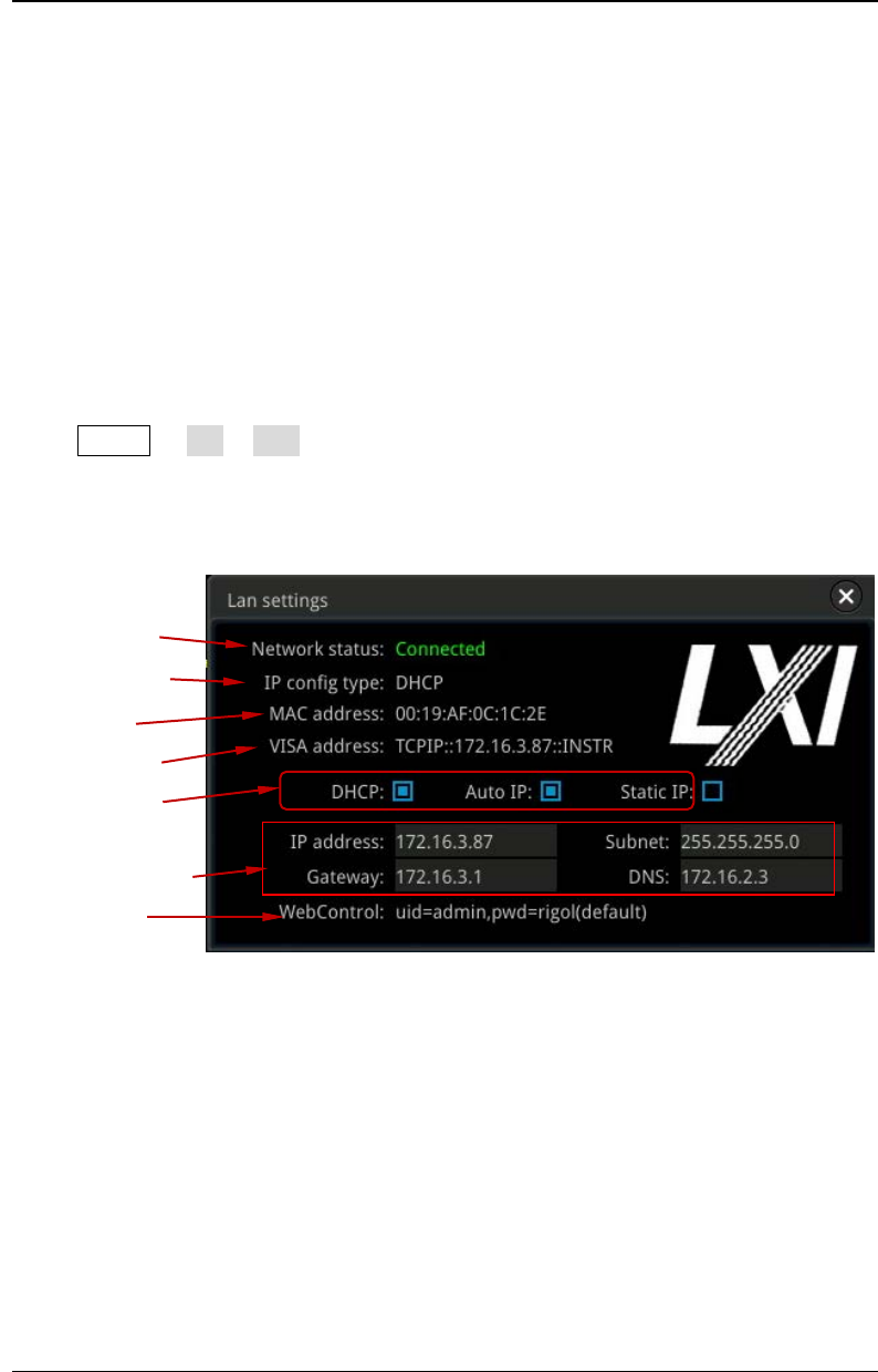
Press Utility IO LAN to open the LAN Settings interface, as shown in the
following figure. You can view the current network settings and configure the
network parameters.
Figure 19-1 Network Connection Setting Interface
Network Status
Different prompts will be displayed according to the current network connection
status.
Network Config Succeeded!
Acquiring IP...
IP Conflict!
Disconnected!
DHCP Config Failed!
Read Status Fail!
Network Status
Current IP Config.
Type
MAC Address
VISA Descriptor
IP Config. Type
Network Parameters
Web Control