
Instructions


Table Of Contents
- Guaranty and Declaration
- Safety Requirement
- MSO5000-E Series Overview
- Document Overview
- Quick Start
- General Inspection
- Appearance and Dimensions
- To Prepare for Use
- Front Panel Overview
- Rear Panel Overview
- Front Panel Function Overview
- User Interface
- Touch Screen Controls
- Parameter Setting Method
- To Use the Kensington Security Lock
- To Use the Built-in Help System
- To View the Option Information and the Option Installation
- To Set the Vertical System
- To Set the Horizontal System
- To Set the Sample System
- To Trigger the Oscilloscope
- Trigger Source
- Trigger LEVEL/Threshold Level
- Trigger Mode
- Trigger Coupling
- Trigger Holdoff
- Noise Rejection
- Trigger Type
- Edge Trigger
- Pulse Trigger
- Slope Trigger
- Video Trigger
- Pattern Trigger
- Duration Trigger
- Timeout Trigger
- Runt Trigger
- Window Trigger
- Delay Trigger
- Setup/Hold Trigger
- Nth Edge Trigger
- RS232 Trigger (Option)
- I2C Trigger (Option)
- SPI Trigger (Option)
- CAN Trigger (Option)
- FlexRay Trigger (Option)
- LIN Trigger (Option)
- I2S Trigger (Option)
- MIL-STD-1553 Trigger (Option)
- Zone Trigger
- Trigger Output Connector
- Operations and Measurements
- Digital Voltmeter (DVM) and Frequency Counter
- Power Analysis (Option)
- Histogram Analysis
- Digital Channel
- Protocol Decoding
- Reference Waveform
- To Enable Ref Function
- To Select the Reference Channel
- To Select the Ref Source
- To Adjust the Ref Waveform Display
- To Save to Internal Memory
- To Clear the Display of the Reference Waveform
- To View Details of the Reference Waveform
- To Reset the Reference Waveform
- Color Setting
- Label Setting
- To Export to Internal or External Memory
- To Import from Internal or External Memory
- Pass/Fail Test
- Waveform Recording & Playing
- Search and Navigation Function
- Display Control
- Function/Arbitrary Waveform Generator (Option)
- Store and Load
- System Utility Function Setting
- Remote Control
- Troubleshooting
- Appendix
- Index
Chapter 1 Quick Start RIGOL
MSO5000-E User Guide 1-11
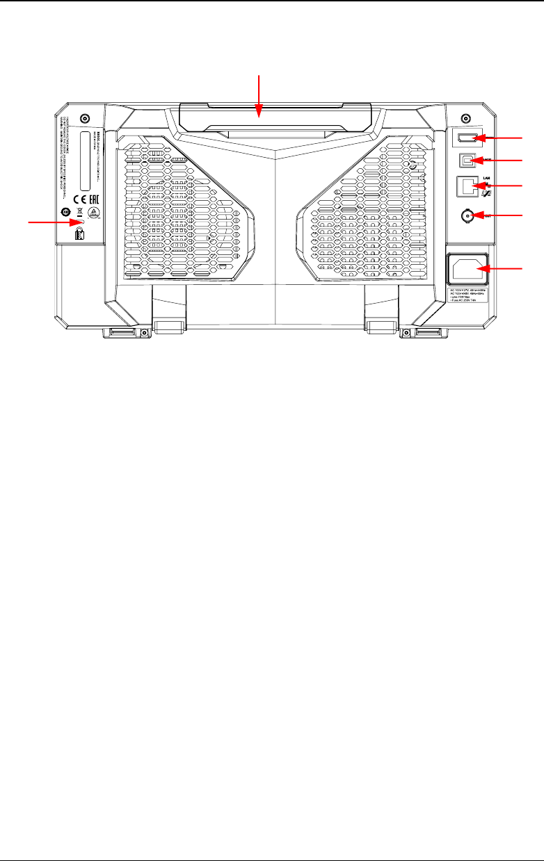
Rear Panel Overview
Figure 1-12 Rear Panel
1. Handle
Rotate the handle upright to carry the instrument easily. Rotate it
downward if you do not need to carry it.
2. HDMI
Through this interface, you can connect the instrument to an external
display equipped with the HDMI interface (e.g. monitor or projector) to
better observe the waveform display clearly. At this time, you can also view
the waveforms on the LCD of the instrument.
3. USB DEVICE Interface
You can connect the instrument to the PC via this interface. Then you can
use the PC software Ultra Scope to send the SCPI commands, the
user-defined programming, or Web Control to control the instrument.
4. LAN Interface
Connect the instrument to network via this interface. The instrument is in
compliance with the standards specified in LXI Device Specification 2011. It
can be used to set up a test system.
When you access to the Internet, you can use the Web Control or PC
software Ultra Scope to send the SCPI commands or use the user-defined
programming to control the instrument. When update is available, you can
perform online upgrading for the system software of the instrument via the
LAN interface. After it is connected to the network, you can print the
waveform displayed on the screen when you use the network printer.
7
2
3
4
5
6
1