
Instructions
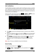


Table Of Contents
- Guaranty and Declaration
- Safety Requirement
- MSO5000-E Series Overview
- Document Overview
- Quick Start
- General Inspection
- Appearance and Dimensions
- To Prepare for Use
- Front Panel Overview
- Rear Panel Overview
- Front Panel Function Overview
- User Interface
- Touch Screen Controls
- Parameter Setting Method
- To Use the Kensington Security Lock
- To Use the Built-in Help System
- To View the Option Information and the Option Installation
- To Set the Vertical System
- To Set the Horizontal System
- To Set the Sample System
- To Trigger the Oscilloscope
- Trigger Source
- Trigger LEVEL/Threshold Level
- Trigger Mode
- Trigger Coupling
- Trigger Holdoff
- Noise Rejection
- Trigger Type
- Edge Trigger
- Pulse Trigger
- Slope Trigger
- Video Trigger
- Pattern Trigger
- Duration Trigger
- Timeout Trigger
- Runt Trigger
- Window Trigger
- Delay Trigger
- Setup/Hold Trigger
- Nth Edge Trigger
- RS232 Trigger (Option)
- I2C Trigger (Option)
- SPI Trigger (Option)
- CAN Trigger (Option)
- FlexRay Trigger (Option)
- LIN Trigger (Option)
- I2S Trigger (Option)
- MIL-STD-1553 Trigger (Option)
- Zone Trigger
- Trigger Output Connector
- Operations and Measurements
- Digital Voltmeter (DVM) and Frequency Counter
- Power Analysis (Option)
- Histogram Analysis
- Digital Channel
- Protocol Decoding
- Reference Waveform
- To Enable Ref Function
- To Select the Reference Channel
- To Select the Ref Source
- To Adjust the Ref Waveform Display
- To Save to Internal Memory
- To Clear the Display of the Reference Waveform
- To View Details of the Reference Waveform
- To Reset the Reference Waveform
- Color Setting
- Label Setting
- To Export to Internal or External Memory
- To Import from Internal or External Memory
- Pass/Fail Test
- Waveform Recording & Playing
- Search and Navigation Function
- Display Control
- Function/Arbitrary Waveform Generator (Option)
- Store and Load
- System Utility Function Setting
- Remote Control
- Troubleshooting
- Appendix
- Index
Chapter 19 System Utility Function Setting RIGOL
MSO5000-E User Guide 19-17
4. Restore Defaults
Press Default to restore the screen saver to the default settings.
Self-check
The oscilloscope supports a variety of self-check functions, including key test, screen
test, and touch test.
Press Utility More More Self Check to enter the self-check menu.
1. Key Test
Press Key Test to enter the keyboard test interface (virtual keypad of the front
panel). At this time, you can press the keys on the front panel to check whether
the virtual keys are highlighted. If yes, it indicates that the keys work normally;
if no, it indicates that there's something wrong with the keys. Press RUN/STOP
for three consecutive times to exit the keyboard test interface.
2. Screen Test
Press Screen Test to enter the screen test interface and check whether the
defective pixel exists. There are 24 screen test interfaces. Press SINGLE to
switch to the next screen test interface. Press RUN/STOP for three consecutive
times to exit the screen test interface.
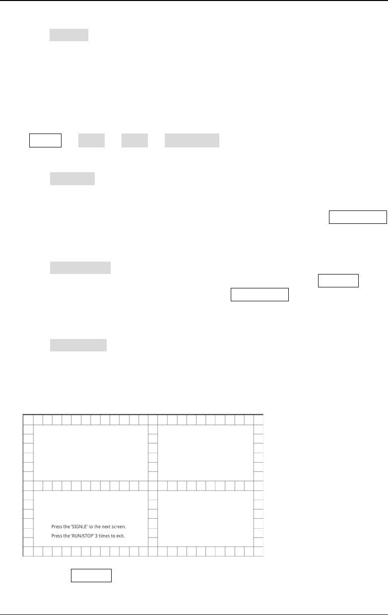
3. Touch Test
Press Touch Test to enter the touch screen test interface first, as shown in the
figure below. Slide with your finger on the screen. If there is a line displaying at
the empty area where you slide on the screen and the box that you tap turns out
to be filled with green background, it indicates that the touch function of this
area is normal.
The press SINGLE to switch to the next touch screen test interface, as shown
in the figure below. At this time, you can pinch or stretch the RIGOL logo on