
Instructions


Table Of Contents
- Guaranty and Declaration
- Safety Requirement
- MSO5000-E Series Overview
- Document Overview
- Quick Start
- General Inspection
- Appearance and Dimensions
- To Prepare for Use
- Front Panel Overview
- Rear Panel Overview
- Front Panel Function Overview
- User Interface
- Touch Screen Controls
- Parameter Setting Method
- To Use the Kensington Security Lock
- To Use the Built-in Help System
- To View the Option Information and the Option Installation
- To Set the Vertical System
- To Set the Horizontal System
- To Set the Sample System
- To Trigger the Oscilloscope
- Trigger Source
- Trigger LEVEL/Threshold Level
- Trigger Mode
- Trigger Coupling
- Trigger Holdoff
- Noise Rejection
- Trigger Type
- Edge Trigger
- Pulse Trigger
- Slope Trigger
- Video Trigger
- Pattern Trigger
- Duration Trigger
- Timeout Trigger
- Runt Trigger
- Window Trigger
- Delay Trigger
- Setup/Hold Trigger
- Nth Edge Trigger
- RS232 Trigger (Option)
- I2C Trigger (Option)
- SPI Trigger (Option)
- CAN Trigger (Option)
- FlexRay Trigger (Option)
- LIN Trigger (Option)
- I2S Trigger (Option)
- MIL-STD-1553 Trigger (Option)
- Zone Trigger
- Trigger Output Connector
- Operations and Measurements
- Digital Voltmeter (DVM) and Frequency Counter
- Power Analysis (Option)
- Histogram Analysis
- Digital Channel
- Protocol Decoding
- Reference Waveform
- To Enable Ref Function
- To Select the Reference Channel
- To Select the Ref Source
- To Adjust the Ref Waveform Display
- To Save to Internal Memory
- To Clear the Display of the Reference Waveform
- To View Details of the Reference Waveform
- To Reset the Reference Waveform
- Color Setting
- Label Setting
- To Export to Internal or External Memory
- To Import from Internal or External Memory
- Pass/Fail Test
- Waveform Recording & Playing
- Search and Navigation Function
- Display Control
- Function/Arbitrary Waveform Generator (Option)
- Store and Load
- System Utility Function Setting
- Remote Control
- Troubleshooting
- Appendix
- Index
Chapter 1 Quick Start RIGOL
MSO5000-E User Guide 1-13
Front Panel Function Overview
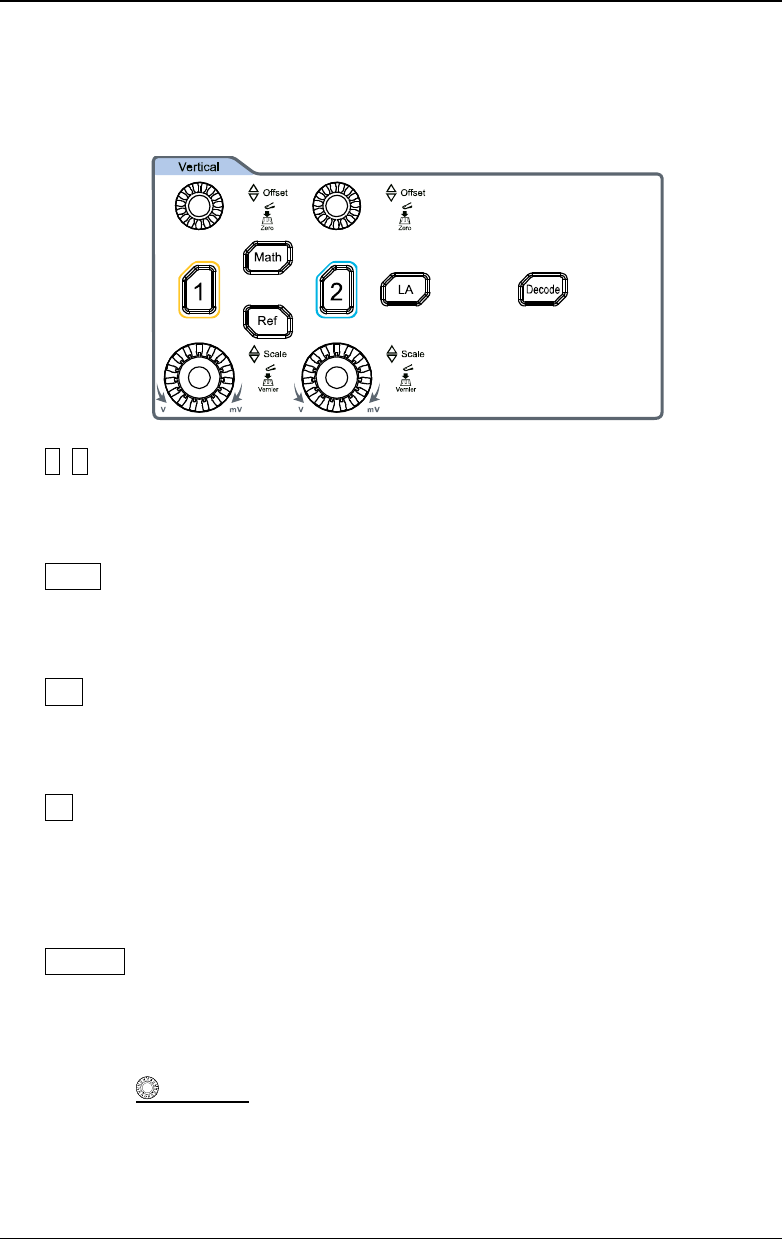
Vertical
1, 2: indicates the analog channel switch key. The two channels are marked by
different colors which are also used to mark both the
corresponding waveforms
of the specified channel on the screen and the channel input connectors.
Math: indicates the math operation key. Press this key to enable the math
operation function. The math operations include A+B, A-
B, A×B, A/B, and FFT.
Besides, you can also set the math operation label.
Ref: indicates the reference waveform key. Press this key to open the
reference waveform setting menu. You can compare the actually measured
waveform with the reference waveform to locate the circuit failure.
LA: indicates the logic analyzer key. Press this key to open the logic analyzer
control menu. You can enable or disable any channel or channel group, modify
the waveform sizes of the digital channel, modify the threshold of the digital
channel, and group
the 16 digital channels. Besides, you can also set a label for
each digital channel.
Decode: indicates the decode key. Press this key to open the decode setting
menu, and then you can set the decode options. MSO5000-E series supports
the parallel decoding and many protocol decodings. (For details, refer to the
descriptions in "
Protocol Decoding").
Vertical
OFFSET: indicates the channel vertical offset knob. You can
rotate the knob to modify the vertical offset of the current channel waveform.
Each analog channel is configured with an independent vertical offset
adjustment knob. Turn it clockwise to increase the offset, and turn it
counterclockwise to decrease the offset. During the modification, the waveform