
Instructions


Table Of Contents
- Guaranty and Declaration
- Safety Requirement
- MSO5000-E Series Overview
- Document Overview
- Quick Start
- General Inspection
- Appearance and Dimensions
- To Prepare for Use
- Front Panel Overview
- Rear Panel Overview
- Front Panel Function Overview
- User Interface
- Touch Screen Controls
- Parameter Setting Method
- To Use the Kensington Security Lock
- To Use the Built-in Help System
- To View the Option Information and the Option Installation
- To Set the Vertical System
- To Set the Horizontal System
- To Set the Sample System
- To Trigger the Oscilloscope
- Trigger Source
- Trigger LEVEL/Threshold Level
- Trigger Mode
- Trigger Coupling
- Trigger Holdoff
- Noise Rejection
- Trigger Type
- Edge Trigger
- Pulse Trigger
- Slope Trigger
- Video Trigger
- Pattern Trigger
- Duration Trigger
- Timeout Trigger
- Runt Trigger
- Window Trigger
- Delay Trigger
- Setup/Hold Trigger
- Nth Edge Trigger
- RS232 Trigger (Option)
- I2C Trigger (Option)
- SPI Trigger (Option)
- CAN Trigger (Option)
- FlexRay Trigger (Option)
- LIN Trigger (Option)
- I2S Trigger (Option)
- MIL-STD-1553 Trigger (Option)
- Zone Trigger
- Trigger Output Connector
- Operations and Measurements
- Digital Voltmeter (DVM) and Frequency Counter
- Power Analysis (Option)
- Histogram Analysis
- Digital Channel
- Protocol Decoding
- Reference Waveform
- To Enable Ref Function
- To Select the Reference Channel
- To Select the Ref Source
- To Adjust the Ref Waveform Display
- To Save to Internal Memory
- To Clear the Display of the Reference Waveform
- To View Details of the Reference Waveform
- To Reset the Reference Waveform
- Color Setting
- Label Setting
- To Export to Internal or External Memory
- To Import from Internal or External Memory
- Pass/Fail Test
- Waveform Recording & Playing
- Search and Navigation Function
- Display Control
- Function/Arbitrary Waveform Generator (Option)
- Store and Load
- System Utility Function Setting
- Remote Control
- Troubleshooting
- Appendix
- Index
Chapter 22 Appendix RIGOL
MSO5000-E User Guide 22-1
Chapter 22 Appendix
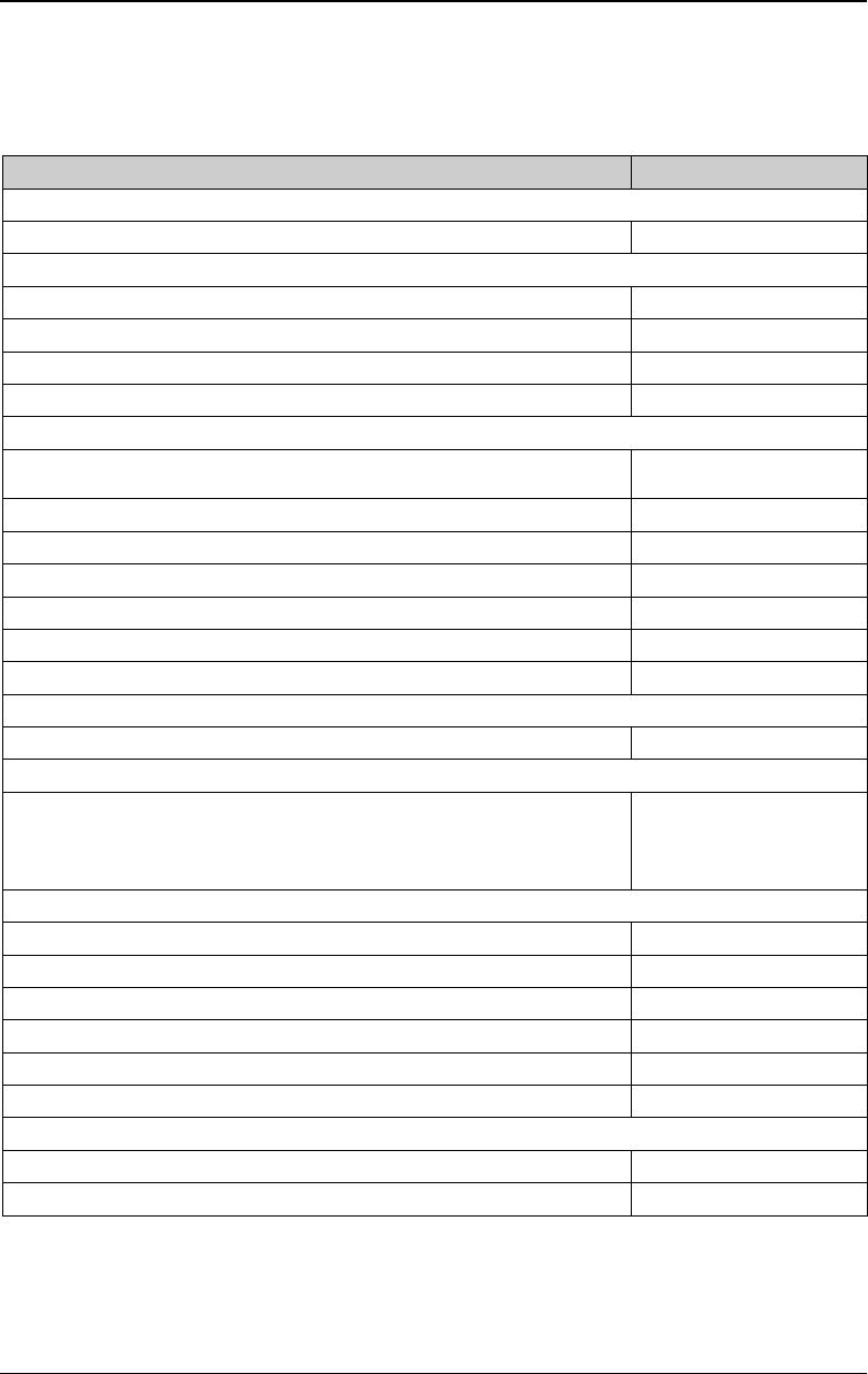
Appendix A: Accessories and Options
Order Information Order No.
Model
MSO5152-E (150 MHz, 4 GSa/s, 100 Mpts, 2+16 CH MSO) MSO5152-E
Standard Accessories
Power Cord Conforming to the Standard of the Destination Country -
USB Cable CB-USBA-USBB-FF-150
2 Passive Probes (350 MHz)
PVP2350
Quick Guide (hard copy) -
Optional Accessories
16-channel active logic probe (dedicated probe for MSO5000-E
series)
PLA2216
Front Panel Protection Cover MSO5000-E-FPC
Rack Mount Kit MSO5000-RM
USB-GPIB Interface Converter USB-GPIB
Near-field Probe NFP-3
Power Analysis Phase Difference Correction Jig RPA246
Digital Oscilloscope Demonstration Plate DK-DS6000
Memory Depth Option
Maximum memory depth up to 100 Mpts MSO5000-E-1RL
Bundle Option
Function and Application Bundle Option, including MSO5000-COMP,
MSO5000-EMBD, MSO5000-AUTO, MSO5000-FLEX,
MSO5000-AUDIO, MSO5000-AERO, MSO5000-E-AWG, and
MSO5000-PWR
MSO5000-E-BND
Serial Protocol Analysis Option
PC Serial Bus Trigger and Analysis (RS232/UART) MSO5000-COMP
Embedded Serial Bus Trigger and Analysis (I2C and SPI) MSO5000-EMBD
Auto Serial Bus Trigger and Analysis (CAN and LIN) MSO5000-AUTO
FlexRay Serial Bus Trigger and Analysis (FlexRay) MSO5000-FLEX
Audio Serial Bus Trigger and Analysis (I2S) MSO5000-AUDIO
MIL-STD-1553 Serial Bus Trigger and Analysis (MIL-STD-1553) MSO5000-AERO
Measurement Application Option
25 MHz Arbitrary Waveform Generator MSO5000-E-AWG
Built-in Power Analysis MSO5000-PWR
Note: For all the mainframes, accessories, and options, please contact the local
office of RIGOL.