
Instructions


Table Of Contents
- Guaranty and Declaration
- Safety Requirement
- MSO5000-E Series Overview
- Document Overview
- Quick Start
- General Inspection
- Appearance and Dimensions
- To Prepare for Use
- Front Panel Overview
- Rear Panel Overview
- Front Panel Function Overview
- User Interface
- Touch Screen Controls
- Parameter Setting Method
- To Use the Kensington Security Lock
- To Use the Built-in Help System
- To View the Option Information and the Option Installation
- To Set the Vertical System
- To Set the Horizontal System
- To Set the Sample System
- To Trigger the Oscilloscope
- Trigger Source
- Trigger LEVEL/Threshold Level
- Trigger Mode
- Trigger Coupling
- Trigger Holdoff
- Noise Rejection
- Trigger Type
- Edge Trigger
- Pulse Trigger
- Slope Trigger
- Video Trigger
- Pattern Trigger
- Duration Trigger
- Timeout Trigger
- Runt Trigger
- Window Trigger
- Delay Trigger
- Setup/Hold Trigger
- Nth Edge Trigger
- RS232 Trigger (Option)
- I2C Trigger (Option)
- SPI Trigger (Option)
- CAN Trigger (Option)
- FlexRay Trigger (Option)
- LIN Trigger (Option)
- I2S Trigger (Option)
- MIL-STD-1553 Trigger (Option)
- Zone Trigger
- Trigger Output Connector
- Operations and Measurements
- Digital Voltmeter (DVM) and Frequency Counter
- Power Analysis (Option)
- Histogram Analysis
- Digital Channel
- Protocol Decoding
- Reference Waveform
- To Enable Ref Function
- To Select the Reference Channel
- To Select the Ref Source
- To Adjust the Ref Waveform Display
- To Save to Internal Memory
- To Clear the Display of the Reference Waveform
- To View Details of the Reference Waveform
- To Reset the Reference Waveform
- Color Setting
- Label Setting
- To Export to Internal or External Memory
- To Import from Internal or External Memory
- Pass/Fail Test
- Waveform Recording & Playing
- Search and Navigation Function
- Display Control
- Function/Arbitrary Waveform Generator (Option)
- Store and Load
- System Utility Function Setting
- Remote Control
- Troubleshooting
- Appendix
- Index
RIGOL Chapter 1 Quick Start
1-14 MSO5000-E User Guide
would move up and down. Meanwhile, the offset information in the
corresponding status label would change accordingly. Press down this knob to
quickly reset the vertical offset to zero.
Vertical
SCALE: indicates the channel vertical scale knob. Modify the
vertical scale of the current channel. Each analog channel is configured with an
independent vertical scale adjustment knob. Turn it clockwise to decrease the
scale, and turn it counterclockwise to increase the scale. During the
modification, the display amplitude of the waveform will enlarge or reduce. The
scale information in the corresponding status label will change accordingly.
Press down this knob to quickly switch the vertical scale adjustment mode
between "Coarse" and "Fine".
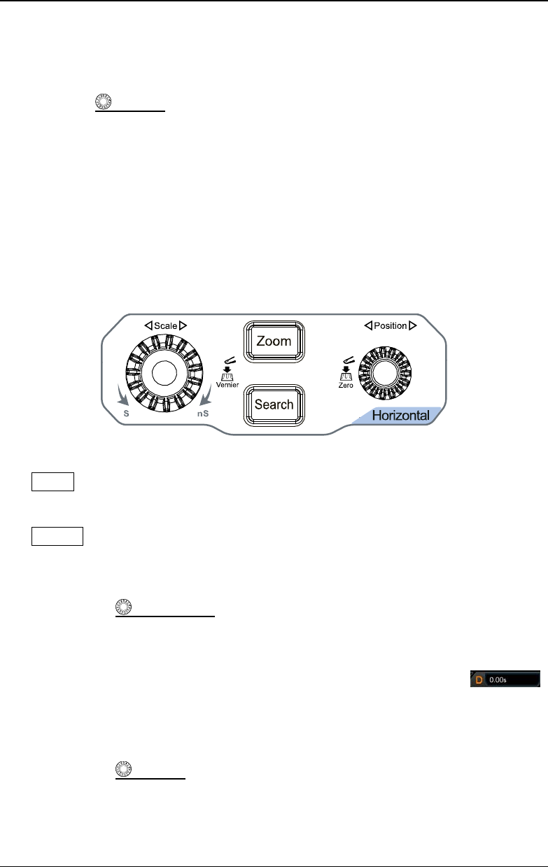
Horizontal
Zoom: indicates the delayed sweep key. Press this key to enable or disable the
delayed sweep function.
Search: indicates the Search key. Press this key to enter the search setting
menu. The search function allows you to search for relevant events from the
collected data based on the search condition that you set.
Horizontal
POSITION: indicates the horizontal position knob. You can
rotate the knob to modify the horizontal position (i.g. trigger position). The
trigger point would move left or right relative to the center of the screen when
you rotate the knob. During the modification, waveforms of all the channels
would move left or right, and the horizontal position message (e.g.
)
at the upper-right corner of the screen would change accordingly. Press down
this knob to quickly reset the horizontal position (or the delayed sweep
position).
Horizontal
SCALE: indicates the horizontal timebase knob. You can rotate
the knob to modify the horizontal timebase. Turn it clockwise to decrease the
timebase, and turn it counterclockwise to increase the timebase. During the
modification, waveforms of all the channels will be displayed in expanded or