
Instructions
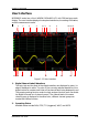
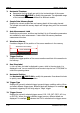
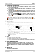


Table Of Contents
- Guaranty and Declaration
- Safety Requirement
- MSO5000-E Series Overview
- Document Overview
- Quick Start
- General Inspection
- Appearance and Dimensions
- To Prepare for Use
- Front Panel Overview
- Rear Panel Overview
- Front Panel Function Overview
- User Interface
- Touch Screen Controls
- Parameter Setting Method
- To Use the Kensington Security Lock
- To Use the Built-in Help System
- To View the Option Information and the Option Installation
- To Set the Vertical System
- To Set the Horizontal System
- To Set the Sample System
- To Trigger the Oscilloscope
- Trigger Source
- Trigger LEVEL/Threshold Level
- Trigger Mode
- Trigger Coupling
- Trigger Holdoff
- Noise Rejection
- Trigger Type
- Edge Trigger
- Pulse Trigger
- Slope Trigger
- Video Trigger
- Pattern Trigger
- Duration Trigger
- Timeout Trigger
- Runt Trigger
- Window Trigger
- Delay Trigger
- Setup/Hold Trigger
- Nth Edge Trigger
- RS232 Trigger (Option)
- I2C Trigger (Option)
- SPI Trigger (Option)
- CAN Trigger (Option)
- FlexRay Trigger (Option)
- LIN Trigger (Option)
- I2S Trigger (Option)
- MIL-STD-1553 Trigger (Option)
- Zone Trigger
- Trigger Output Connector
- Operations and Measurements
- Digital Voltmeter (DVM) and Frequency Counter
- Power Analysis (Option)
- Histogram Analysis
- Digital Channel
- Protocol Decoding
- Reference Waveform
- To Enable Ref Function
- To Select the Reference Channel
- To Select the Ref Source
- To Adjust the Ref Waveform Display
- To Save to Internal Memory
- To Clear the Display of the Reference Waveform
- To View Details of the Reference Waveform
- To Reset the Reference Waveform
- Color Setting
- Label Setting
- To Export to Internal or External Memory
- To Import from Internal or External Memory
- Pass/Fail Test
- Waveform Recording & Playing
- Search and Navigation Function
- Display Control
- Function/Arbitrary Waveform Generator (Option)
- Store and Load
- System Utility Function Setting
- Remote Control
- Troubleshooting
- Appendix
- Index
RIGOL Chapter 1 Quick Start
1-22 MSO5000-E User Guide
18. CH2 Status Label
Displays the status of CH2.
Displays the vertical scale of CH2. That is, the voltage value per grid of CH2
in the vertical axis.
Displays the offset of CH2, i.g. the vertical offset of CH2 waveform.
Different labels will be displayed according to the current channel setting.
For example, if you select "DC" for channel coupling,
is displayed; if you
enable the bandwidth limit,
is displayed.
19. CH1 Status Label
Displays the status of CH1.
Displays the vertical scale of CH1. That is, the voltage value per grid of CH1
in the vertical axis.
Displays the offset of CH1, i.g. the vertical offset of CH1 waveform.
Different labels will be displayed according to the current channel setting.
For example, if you select "DC" for channel coupling,
is displayed; if you
enable the bandwidth limit,
is displayed.
20. Analog Channel Label/Waveform
Different channels are marked with different colors. The color of the channel
label is the same as that of the waveform.
21. Function Navigation
Enable the touch screen and then tap this icon to enable the function navigation.
Touch Screen Controls
MSO5000-E series provides a 9-inch super large capacitive touch screen, which
supports multi-touch and gesture operation. It has strong waveform display
capability and excellent user experience. It features great convenience, high
flexibility, and great sensitivity. The actions supported by the touch screen controls
include tapping, pinching & stretching, dragging, and rectangle drawing.
Tip
The touch screen function is available for all the menus displayed on the screen
and the buttons enabled. In this manual, key operation descriptions are illustrated
in details, and as for the touch screen function about some operations, refer to
descriptions in relevant chapters.