
Instructions


Table Of Contents
- Guaranty and Declaration
- Safety Requirement
- MSO5000-E Series Overview
- Document Overview
- Quick Start
- General Inspection
- Appearance and Dimensions
- To Prepare for Use
- Front Panel Overview
- Rear Panel Overview
- Front Panel Function Overview
- User Interface
- Touch Screen Controls
- Parameter Setting Method
- To Use the Kensington Security Lock
- To Use the Built-in Help System
- To View the Option Information and the Option Installation
- To Set the Vertical System
- To Set the Horizontal System
- To Set the Sample System
- To Trigger the Oscilloscope
- Trigger Source
- Trigger LEVEL/Threshold Level
- Trigger Mode
- Trigger Coupling
- Trigger Holdoff
- Noise Rejection
- Trigger Type
- Edge Trigger
- Pulse Trigger
- Slope Trigger
- Video Trigger
- Pattern Trigger
- Duration Trigger
- Timeout Trigger
- Runt Trigger
- Window Trigger
- Delay Trigger
- Setup/Hold Trigger
- Nth Edge Trigger
- RS232 Trigger (Option)
- I2C Trigger (Option)
- SPI Trigger (Option)
- CAN Trigger (Option)
- FlexRay Trigger (Option)
- LIN Trigger (Option)
- I2S Trigger (Option)
- MIL-STD-1553 Trigger (Option)
- Zone Trigger
- Trigger Output Connector
- Operations and Measurements
- Digital Voltmeter (DVM) and Frequency Counter
- Power Analysis (Option)
- Histogram Analysis
- Digital Channel
- Protocol Decoding
- Reference Waveform
- To Enable Ref Function
- To Select the Reference Channel
- To Select the Ref Source
- To Adjust the Ref Waveform Display
- To Save to Internal Memory
- To Clear the Display of the Reference Waveform
- To View Details of the Reference Waveform
- To Reset the Reference Waveform
- Color Setting
- Label Setting
- To Export to Internal or External Memory
- To Import from Internal or External Memory
- Pass/Fail Test
- Waveform Recording & Playing
- Search and Navigation Function
- Display Control
- Function/Arbitrary Waveform Generator (Option)
- Store and Load
- System Utility Function Setting
- Remote Control
- Troubleshooting
- Appendix
- Index
RIGOL Chapter 2 To Set the Vertical System
2-2 MSO5000-E User Guide
To Enable or Disable the Analog Channel
Enable the analog channel:
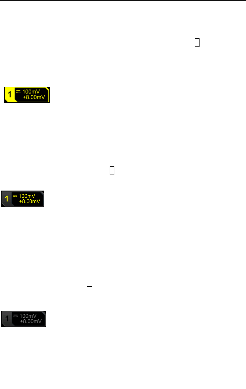
Connect a signal to the channel connector of CH1, and then press 1 in the vertical
control area (Vertical) on the front panel to enable CH1. Then, the backlight of the
channel is illuminated. At this point, the channel setting menu is displayed at the
right section of the screen and the channel is activated. The channel status label at
the bottom of the screen is shown in the figure below. You can also enable the touch
screen to tap the channel status label to enable the channel.
The information displayed in the channel status label is related to the current channel
setting but irrelevant with the on/off status of the channel. After the channel is
turned on, modify the parameters such as the vertical scale, horizontal timebase,
trigger mode, and trigger level according to the input signal for easy observation and
measurement of the waveform.
If CH1 is enabled but not activated, the channel status label is shown in the following
figure. To activate the channel, press 1 on the front panel in the vertical control area
(Vertical) or enable the touch screen to tap the waveform activation channel
displayed on the screen.
Disable the analog channel:
If the setting menu of the channel that needs to be disabled (the current channel is
activated) is displayed at the right section of the screen, press the channel key to
disable the channel. If the setting menu of the channel that needs to be disabled is
not displayed at the right section of the screen, first open the setting menu of the
channel to be disabled (activate the channel), then press the channel key to disable
the channel. You can also enable the touch screen to tap the channel status label to
disable the channel. For example, if CH1 and CH2 are enabled, and CH2 channel
setting menu is displayed on the screen, then if you need to disable CH1, first
activate CH1, and then press 1 or enable the touch screen to tap the CH1 channel
status label to disable CH1. If CH1 is disabled, the channel status label is shown in
the following figure.