
Instructions


Table Of Contents
- Guaranty and Declaration
- Safety Requirement
- MSO5000-E Series Overview
- Document Overview
- Quick Start
- General Inspection
- Appearance and Dimensions
- To Prepare for Use
- Front Panel Overview
- Rear Panel Overview
- Front Panel Function Overview
- User Interface
- Touch Screen Controls
- Parameter Setting Method
- To Use the Kensington Security Lock
- To Use the Built-in Help System
- To View the Option Information and the Option Installation
- To Set the Vertical System
- To Set the Horizontal System
- To Set the Sample System
- To Trigger the Oscilloscope
- Trigger Source
- Trigger LEVEL/Threshold Level
- Trigger Mode
- Trigger Coupling
- Trigger Holdoff
- Noise Rejection
- Trigger Type
- Edge Trigger
- Pulse Trigger
- Slope Trigger
- Video Trigger
- Pattern Trigger
- Duration Trigger
- Timeout Trigger
- Runt Trigger
- Window Trigger
- Delay Trigger
- Setup/Hold Trigger
- Nth Edge Trigger
- RS232 Trigger (Option)
- I2C Trigger (Option)
- SPI Trigger (Option)
- CAN Trigger (Option)
- FlexRay Trigger (Option)
- LIN Trigger (Option)
- I2S Trigger (Option)
- MIL-STD-1553 Trigger (Option)
- Zone Trigger
- Trigger Output Connector
- Operations and Measurements
- Digital Voltmeter (DVM) and Frequency Counter
- Power Analysis (Option)
- Histogram Analysis
- Digital Channel
- Protocol Decoding
- Reference Waveform
- To Enable Ref Function
- To Select the Reference Channel
- To Select the Ref Source
- To Adjust the Ref Waveform Display
- To Save to Internal Memory
- To Clear the Display of the Reference Waveform
- To View Details of the Reference Waveform
- To Reset the Reference Waveform
- Color Setting
- Label Setting
- To Export to Internal or External Memory
- To Import from Internal or External Memory
- Pass/Fail Test
- Waveform Recording & Playing
- Search and Navigation Function
- Display Control
- Function/Arbitrary Waveform Generator (Option)
- Store and Load
- System Utility Function Setting
- Remote Control
- Troubleshooting
- Appendix
- Index
Chapter 4 To Set the Sample System RIGOL
MSO5000-E User Guide 4-9
LA Sample Rate
LA sampling is the process of sampling on the compared digital signals at a certain
time interval. LA sample rate is the reciprocal of the time interval. For example, if the
LA sample rate is 500 MSa/s, it indicates that the oscilloscope will make data
acquisition on the digital signals at an interval of 2 ns. The maximum LA sample rate
of the oscilloscope is 1 GSa/s, and its display value is related to the sample rate of the
current analog channel.
Note:
The digital signals here mentioned refers to the signal obtained from the
comparison between the input signal and the user-defined threshold level. The
rule of the comparison is that when the amplitude of the input signal is greater
than the threshold level, it is judged to be the logic high level; when the
amplitude of the input signal is smaller than the threshold level, it is judged to
be the logic low level.
LA sample rate is displayed under the LA SampleRate menu. To indirectly
modify the LA sample rate, rotate the Horizontal
SCALE knob to adjust
the horizontal timebase or modify the memory depth.
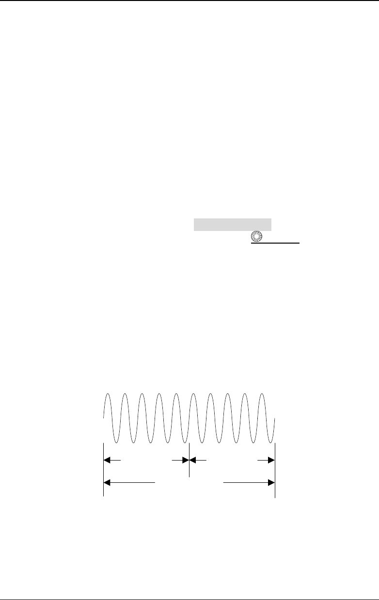
Memory Depth
Memory depth refers to the number of points of the oscilloscope that can store in one
trigger acquisition. It reflects the storage capability of the acquisition storage. This
oscilloscope is equipped with memory depth of up to 100 Mpts (option).
T
Trigger Point
Pre-sample Delayed Sample
Memory Depth
Figure 4-4 Memory Depth
The following equation shows the relations among memory depth, sample rate, and
horizontal timebase scale:
MDepth SRate TScale HDivs=××
MDepth
——indicates the memory depth. The unit is pts.