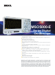
MSO5000-E Series Digital Oscilloscope Analog bandwidth: 150 MHz 2 analog channels, 1 EXT channel, and a standard configuration of 16 digital channels (required to purchase the probe) Up to 4 GSa/s real-time sample rate Up to 100 Mpts memory depth (option) High waveform capture rate (over 300,000 wfm/s) Auto measurement of 41 waveform parameters; full-memory hardware measurement function A variety of serial protocol triggers and decodes Up to 450,000 frames of hardware real-time and ceaseless waveforms reco
MSO5000-E Series Digital Oscilloscope 2
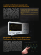
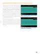
Small Body, Big Use The innovative physical appearance of the instrument and the thin design in both sides of the instrument not only make its LCD display prominent but also keeps its shape delicate, making it portable and easy to operate.
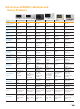
Overview of RIGOL's Medium-end Series Products MSO/DS2000A MSO/DS4000 MSO5000 MSO5000-E DS6000 MSO/DS7000 Analog Channel+Digital Channel 2+16 4+16 2/4+16 2+16 4 4+16 Analog Bandwidth 70 MHz to 300 MHz 100 MHz to 500 MHz 70 MHz to 350 MHz 150MHz 600 MHz to 1 GHz 100 MHz to 500 MHz 2 GSa/s 4 GSa/s 8 GSa/s 4 GSa/s 5 GSa/s 10 GSa/s 56 Mpts (optional) 140 Mpts > 52,000 wfms/s > 110,000 wfms/s 200 Mpts (optional) >500,000 wfms/s 100 Mpts (optional) >300,000 wfms/s 65,000 200,000
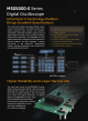
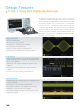
Design Features 7-into-1 Integrated Digital Oscilloscope In today's integrated design field, a highly integrated comprehensive digital oscilloscope has become a useful tool for design engineers.
4.Arbitrary Waveform Generator (Option) ·Standard configuration of one waveforms output channels for the hardware, and only AWG option is required to be ordered ·13 pre-defined waveforms ·Up to 25 MHz frequency ·Up to 200 MSa/s sample rate ·Advanced modulation, sweep, and burst signal output supported 5.
Excellent Sample Bandwidth Ratio Bandwidth and the sample rate are two key technical specifications that engineers take priority in choosing the digital oscilloscope. Bandwidth determines the maximum frequency that the oscilloscope can acquire. The higher the bandwidth of the oscilloscope, the better the oscilloscope can keep the steep, fast, abundant harmonics components and energies of the signal under test.
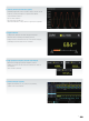
Hardware Full Memory Auto Measurement The auto measurement is the basic tool for engineers to make a rapid analysis of the signals, and it requires more efficient measurement process and accurate measurement results. MSO5000-E supports hardware full memory auto measurement, provides measurements of 41 waveform parameters, supports displaying the statistics and analysis of the measurement results for 10 items.
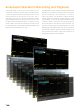
Hardware Waveform Recording and Playback The memory depth is one of the key specifications of the The MSO5000-E series provides ceaseless recording and oscilloscope. However, whatever high the memory depth, playback for a maximum of 450,000 frames of hardware it cannot be guaranteed that all the signals that users are real-time waveforms. This specification is second to concerned about can be captured in one time. This is none in the industry.
Hardware Pass/Fail Test The MSO5000-E series is equipped with hardware pass/ fail test function as the standard configuration, which can be used in signal monitoring for a long time, signal monitoring during design, and signal test in the production line. You can set the test mask based on the known "standard" waveform, and then compare the signal under test with the "standard" waveform to display the statistics on the test results.
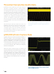
A Variety of Triggers and Protocol Decodings MSO5000-E series digital oscilloscope provides powerful trigger functions, including Edge trigger, Pulse trigger, Slope trigger, Video trigger, Pattern trigger, Duration trigger, Timeout trigger, Runt trigger, Window trigger, Delay trigger, Setup/Hold trigger, Nth Edge trigger, and serial protocol trigger. These triggers can help engineers accurately and quickly capture and identify the signals of great interest.
Power Analysis (Option) To cater to the increasing test demand for the switch power supply and the power component, we configure the MSO5000-E series with the optional built-in power analysis software. The current power analysis software can complete the power quality analysis and ripple analysis. The power analysis software can help engineers analyze the commonly used power parameters rapidly and accurately, without needing to make tedious configurations manually or do complicated formula calculation.
Remote Control Software The Web Control software is a standard configuration for the control in the software are consistent with that in the MSO5000-E series. You can use the software to migrate the MSO5000-E series. You can use the mouse to tap the instrument control and waveform analysis to the PC, and then keys or knobs in the Web Control interface to complete click the mouse to operate easily. the waveform control, measurement, and analysis.
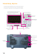
User-defined One-key Quick Operation There is a dedicated Quick key on the front panel of the MSO5000-E series, enabling you to customize the function of the key and complete the commonly used operation quickly. With the customized setting of the Quick key, you can quickly capture the screen image, realize waveform saving, setup saving, all measurement, reset measurement statistics, reset pass/fail test statistics, printing, email sending, waveform recording, group saving, and etc.
RIGOL Probes and Accessories Supported by the MSO5000-E Series ·RIGOL Passive Probes Model Type Highimpedance Probe Description Model Highvoltage Probe 1X: DC ~ 35 MHz 10X: DC ~ 150 MHz Compatibility: All models of RIGOL's digital oscilloscopes RP1010H PVP2150 1X: DC ~ 35 MHz 10X: DC ~ 350 MHz Highimpedance Compatibility: All models of RIGOL's digital Probe oscilloscopes Highimpedance Probe DC ~ 500 MHz Compatibility: All models of RIGOL's digital oscilloscopes RP3500A Highvoltage Probe 16 Hi
·RIGOL Active and Current Probes Model Type Current Probe RP1001C Description BW: DC ~ 300 kHz Maximum Input DC: ±100 A AC P-P: 200 A AC RMS: 70 A Compatibility: All models of RIGOL's digital oscilloscopes Type Description Power Supply Power supply for RP1003C, RP1004C, and RP1005C; supporting 4 channels. Highvoltage Differential Probe BW: 25 MHz Max. voltage ≤ 1400 Vpp Compatibility: All models of RIGOL's digital oscilloscopes Highvoltage Differential Probe BW: 50 MHz Max.
Specifications All the specifications are guaranteed except the parameters marked with "Typical" and the oscilloscope needs to operate for more than 30 minutes under the specified operation temperature. Overview of the MSO5000-E Series Technical Specifications Model Analog Bandwidth Rising Time (typical) MSO5152-E Sampling Mode 150 MHz ≤2.
Horizontal System--Analog Channel Horizontal System--Analog Channel 150 MHz Range of Time Base 5 ns/div~1 ks/div Support fine adjustment Time Base Resolution 10 ps Time Base Accuracy ±10 ppm ± 10 ppm/year before ≥1/2 screen width triggering Time Base Delay Range after 1 s to 100 div triggering Time Interval (△T) ±(1 sample interval) ± (2 ppm×readout)±50 ps Measurement Inter-channel Offset ±100 ns Correction Range YT Default XY X = Channel 1, Y = Channel 2 Horizontal Mode SCAN Time base ≥200 ms/div, availab
Trigger Level Range Internal: EXT EXT/5 AC Line ± 5 div from the center of the screen ±1V ±5V Fixed 50% Trigger Type Trigger Type Zone Trigger Trigger Type Edge Pulse Slope Video Pattern Duration Timeout Runt Window Delay Setup/Hold Nth Edge RS232/UART (Option) I2C (Option) SPI (Option) CAN (Option) FlexRay (Option) 20 Trigger in the rectangle area drawn manually, supporting trigger zone A and trigger zone B.
LIN (Option) I2S (Option) MIL-STD-1553 (Option) MSO5000-AUTO option Trigger on the Sync, ID, Data (length settable), Data&ID, Wakeup, Sleep, and Error of the LIN bus signal (up to 20 Mb/s). Source channel: CH1~CH2, D0~D15 MSO5000-AUDIO option Trigger on 2's complement data of audio left channel, right channel, or either channel (=, ≠, >, <, <>, > <). The available alignment modes include I2S, LJ, and RJ.
Source CH1~CH2, D0~D15 (only available for A&&B, A||B, !A, and A^B), Math1~Math4, and Ref1~Ref10 Color Grade Support Math and FFT Enhanced FFT Record Length Window Type Peak Search Max. 1 Mpts Rectangular (default), Blackman-Harris, Hanning, Hamming, Flattop, and Triangle. a maximum of 15 peaks, confirmed by the settable threshold and offset threshold set by users Waveform Analysis Waveform Analysis Waveform Recording Store the signal under test in segments according to the trigger events, i.g.
MSO5000-AUDIO option Decode I2S audio bus left channel data and right channel data, supporting 4-32 bits. The alignment modes include I2S, LJ, and RJ. Source channel: CH1~CH2, D0~D15 MSO5000-AERO option Decode the MIL-STD-1553 bus signal's data word, command word, and status word (address+last 11 bits).
Amplitude DC Offset Output Range 20 mVpp~5 Vpp (HighZ), 10 mVpp~2.5 Vpp (50 Ω) Resolution 100 uV or 3 bits (whichever is greater) Accuracy ±(2% of setting+1 mV) (Frequency=1 kHz) Range ±2.5 V (HighZ), ±1.25 V (50 Ω) Resolution 100 uV or 3 bits (whichever is greater) Accuracy ±(2% of offset setting+5 mV+0.5% of amplitude) AM, FM, FSK Modulating Waveforms: Sine, Square, Triangle, and Noise.
Quick Reset of Statistics Quickly reset all the measurement statistics data and measurement counts. Quickly reset all the statistics information in PassFail function. Quick Waveform Recording Quickly start or stop the waveform recording. Quick Email Sending Quickly send the Email based on the set email address. Quick Print Quickly perform the print operation based on the current printer settings.
Non-operating Operating Below +30℃: ≤90% RH (without condensation) +30℃ to +40℃, ≤75% RH (without condensation) +40℃ to +50℃, ≤45% RH (without condensation) Below 65℃: ≤90% RH (without condensation) Below 3,000 Non-operating Below 15,000 Operating Humidity Range Altitude Warranty and Calibration Interval Warranty and Calibration Interval Warranty Recommended Calibration Interval 3 years 18 months Regulations Regulations Electromagnetic Compatibility Safety Vibration Shock Compliant with EMC DIR
Order Information Order Information Order No.
HEADQUARTER EUROPE NORTH AMERICA JAPAN RIGOL TECHNOLOGIES, INC. No.8 Keling Road, New District,Suzhou, JiangSu,P.R.China Tel:+86-400620002 Email:info@rigol.com RIGOL TECHNOLOGIES EU GmbH Lindbergh str. 4 82178 Puchheim Germany Tel: 0049-89/89418950 Email: info-europe@rigol.com RIGOL TECHNOLOGIES, USA INC. 8140 SW Nimbus Ave. Beaverton, OR 97008 Tel: 877-4-RIGOL-1 Fax: 877-4-RIGOL-1 Email: info@rigol.com RIGOL TECHNOLOGIES JAPAN, LLC MJ Bldg.