
User manual


RIGOL
12 MSO7000/DS7000 Quick Guide
English
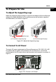
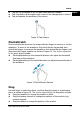
Figure 8 To Connect the Active Probe
3. Use the probe auxiliary equipment to connect the probe front to the circuit
under test. For details about the probes, refer to
RP7000 Series Active
Probe User's Guide
.
After connecting the active probe, you can perform probe calibration and offset
voltage adjustment if necessary. For detailed procedures, refer to the
descriptions of the active probe in user's guide.
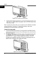
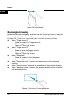
Connect the logic probe:
1. Connect the single-wire terminal of the logic probe to the digital channel
input terminal on the front panel of the oscilloscope in the correct direction,
as shown in Figure 9.
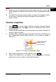
2. Connect the other terminal of the logic probe to the signal terminal under
test. RIGOL's MSO7000 series has a standard configuration of a logic
probe RPL2316. To apply to different application scenarios, RPL2316
provides three connection methods to connect the signal under test. For
details, refer to
RPL2316 Logic Probe User’s Guide
.
Figure 9 To Connect the Logic Probe