
Instructions


Chapter 10 Digital Channel RIGOL
MSO7000/DS7000 User's Guide 10-1
Chapter 10 Digital Channel
MSO7000 series oscilloscope has a standard configuration of the logic analyzer (LA)
function, and it has 16 digital channels. The default channel label is D15-D0. The
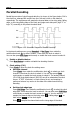
oscilloscope compares the voltages acquired in each sample with the preset logic
threshold. If the voltage of the sample point is greater than the threshold, it will be
stored as logic 1; otherwise, it will be stored as logic 0. The oscilloscope displays
logic levels ("1" and "0") in the form of a graph for you to easily detect and analyze
the errors in circuit design (hardware design and software design).
Before using the digital channels, connect the oscilloscope and the device under test
using RPL2316 logic probe provided in the accessories. To apply to different
application scenarios, RPL2316 provides three connection methods to connect the
signal under test. For details, refer to
RPL2316 Logic Probe User’s Guide
.
Note: The digital channel input terminal does not support hot plug. Please do not
insert or pull out the logic probe when the instrument is powered on.
Contents in this chapter:
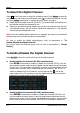
To Select the Digital Channel
To Enable/Disable the Digital Channel
To Set the Threshold
Auto Arrangement Setting
To Set the Waveform Display Size
To Set the Label
Group Setting
Waveform Color of the Digital Channel