
Instructions


RIGOL Chapter 11 Protocol Decoding
11-2 MSO7000/DS7000 User's Guide
Parallel Decoding
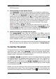
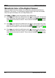
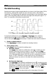
Parallel bus consists of clock line and data line. As shown in the figure below, CLK is
the clock line, whereas Bit0 and Bit1 are the 0 bit and 1st bit on the data line
respectively. The oscilloscope will sample the channel data on the rising edge, falling
edge, or the rising/falling edge of the clock and judge each data point (logic "1" or
logic "0") according to the preset threshold level.
Figure 11-1 Schematic Diagram of Parallel Decoding
In the decode setting menu, press Decode1 Bus Type, then rotate the
multifunction knob to select "Parallel". Press down the knob to select it.
You can also press Bus Type continuously or enable the touch screen to select it.
1. Enable or disable the bus
Press Bus Status to enable or disable the decoding function.
2. Clock setting (CLK)
Press Clock to enter the clock line setting menu.
Set clock channel
Press Clock, then rotate the multifunction knob to select any clock
channel. Press down the knob to select it. You can also press Clock
continuously or enable the touch screen to select it. The analog channel
(CH1-CH4) and digital channel (D0-D15) can all be selected as the clock
source. If "OFF" is selected, no clock channel is set, and sampling is
performed when a hop occurs to the data of the data channel during
decoding.
Set the clock edge type
Press CLK Edge, then rotate the multifunction knob to select the clock
edge type. Press down the knob to select it. You can also press CLK Edge
continuously or enable the touch screen to select it. You can select to
sample the channel data on the rising edge ( ), falling edge ( ), or
both edges ( ) of the clock signal.
Rising : samples the channel data on the rising edge of the clock.