
Instructions


RIGOL Chapter 11 Protocol Decoding
11-14 MSO7000/DS7000 User's Guide
I2C Decoding (Option)
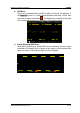
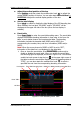
I2C serial bus consists of the clock line (SCLK) and the data line (SDA).
SCL: samples SDA on the rising or falling edge of the clock.
SDA: indicates the data channel.
SCLK
SDA
Figure 11-5 I2C Serial Bus
In the decode setting menu, press Decode1 Bus Type, then rotate the
multifunction knob to select "I2C". Press down the knob to select it. You can also
press Bus Type continuously or enable the touch screen to select it.
1. Enable or disable the bus
Press Bus Status continuously to enable or disable the decoding function.
2. Quickly apply I2C trigger settings to I2C decoding
Press Copy Trig to copy the clock signal and data signal settings (SCL and SDA)
of the current I2C trigger settings and apply them to I2C decoding function (SCL
and SDA). For analog channels, the threshold level settings will also be copied.
3. Source setting
Press Sources to enter the source setting menu.
Set the clock channel source and the threshold
Press SCL and rotate the multifunction knob to select the desired
source of the clock channel, and then press down the knob to select it.
You can also press SCL continuously or enable the touch screen to
select it. The available channels include CH1-CH4 and D0-D15.
When you select the analog channel (CH1-CH4), press SCL Thre, then
rotate the multifunction knob or use the pop-up numeric keypad to
adjust the threshold of the clock channel. When you modify the
threshold of the clock channel, a dotted line displaying the current
threshold level is displayed on the screen. The dotted line disappears in
about 2 s after you stop modifying the threshold.
Set the data channel source and the threshold
Use the same method to select the source of the data channel and set the
threshold (only when the source of the data channel is set to an analog
channel (CH1-CH4)).
Exchange sources