MEMO Operating Manual
TABLE OF CONTENT 1. PREFACE 3 2. IMPORTANT INFORMATION 8 Explanations to symbols ...........................................................................................................................................................................3 Spare part overview exploded diagram .....................................................................................................................................................4 Spare part overview article numbers .............................
24 9. MODES 25 10. MENU OVERVIEW V1.40 26 11. WARNINGS AND ERROR MESSAGES 28 12. CLEANING AND MAINTENANCE 29 13. PROBLEMS - POSSIBLE SOLUTIONS 32 14. INSTRUCTIONS FOR COMMISSIONING PROTOCOL 33 15. GUARANTEE 35 RIKA room sensor/RIKA radio room sensor .........................................................................................................................................24 RIKA phone option – GSM ...................................................................................
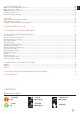
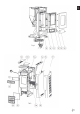
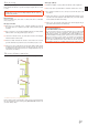
Spare part overview exploded diagram
EN 65 4 |5
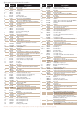
Spare part overview article numbers Nr. 1 2 3 4*** 4 5 6**** 6 6 6 6 *** Art.Nr.
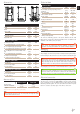
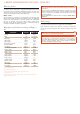
Technical data Technical data Heating power range [kW] 2,4 - 9 Room heating capacity (depending on house insulation) [m³] 50 - 240 [kg/h] bis 2,2 [kg] 21 [V]/[Hz] 230/50 [W] ~ 20 Fuse [A] 2,5 AT Efficiency [%] 92,1 CO2 [%] F-H R-H F- R- H Fuel consumption B T F-S R-S Dimensions Pellet container capacity Electric supply Average electrical input 11,1 Height [mm] 978 CO-emission on 13% OO [mg/mN ] 34 Width [mm] 490 Dust emission [mg/mN ] 22 Corpus depth [mm] 544
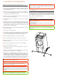
2. IMPORTANT INFORMATION General warning and safety information Observance of the introductory general warning information is imperative. Q Read the entire manual thoroughly before installing and putting the stove into service. Observe the national provisions and laws as well as the regulations and rules applicable locally. Q RIKA stoves should only be installed in rooms with normal humidity (dry areas according to VDE 0100 Part 200).
Prior to set up Floor bearing capacity Ensure that the substructure is capable of bearing the weight of the stove prior to set-up. Note No modifications may be made to the firing installation. This also leads to loss of warranty and guarantee. Q Suitable for multiple occupancy. (Note the different country regulations.) Q These may only be operated with the combustion chamber door closed. Q The combustion chamber door is to be kept closed when the stove is not in operation.
3. BRIEF INFORMATION ON FUEL - PELLETS What are pellets? Wood pellets are a standardised fuel. Every manufacturer must adhere to certain conditions in order to enable flawless, energy-efficient heating. Pellets are made from wooden waste, from sawmills and planning workshops, as well as from residue from forestry operations. These “starting products” are crushed, dried, and pressed into Pellet “Fuel” without any bonding agent.
Operating comfort The microprocessor-controlled combustion regulation optimises the interaction of flue gas blower and screw using the current combustion chamber temperature. This guarantees optimum combustion and operating status. All function can be regulated centrally using the integrated operating unit. The intuitive graphic interface permits easy operation; all the settings can be made quickly and simply.
5. INSTALLING THE STOVE General information Note Only use heat-resistant sealing materials as well as corresponding sealing strips, heat-resistant silicon and rock wool. Connecting to a steel chimney The connection must be calculated and shown with EN13384-1 and EN13384-2. Use only insulated (double) stainless steel tubes (flexible aluminum or steel tubes are not permitted). Note Assembly may only be performed by authorised specialist companies.
Open the 4 vertical hexagonal screws used to attach the convection fins and lift the convection fins up and away. Note Only work on the unit when the mains plug has been disconnected and the stove has cooled completely. #8 Note During assembly / dismantling do not allow objects (screws etc.) to fall into the pellet container – they can block the screw conveyor and damage the stove. Note During any conversion work, take particular care of your fingers and any panels and stove attachments.
7. INTERNAL CONTROLS The stove has a modern programmable microprocessor control. The individual unit functions can be preset by the user via the internal controls located in the right casing (keyboard with operating display). Basics Note Manipulation of hardware components may only be performed by trained specialist dealers and service.
display Cleaning and tipping during operation description The automatic cleaning process is conducted every hour for approx. 2 minutes. During this phase the air vents that are necessary for combustion are blown clean. EASY OFF IGNIT START EASY 35 Pressing starts the unit. This is shown by IGNITE in the display; this is replaced by START after a brief time.
Extended heating operation - HEAT MODE - comfort funktions In addition to the basic functions of simple heating operation, the RIKA pellet stove provides extra comfort functions. However, before you can use the comfort functions such as frost protection, installation of an external room thermostat, regulation of the stove mobile telephone, child safety device, you have to change from simple heating to comfort mode.
EN Menu structure and main menu level MENU switc h b etween EA S Y and HEA T m odes press m enu k ey f or at least 5 sec onds EASY O FF key MENU MENU HEAT O FF MODE MENU sensor TIME MENU display EASY OFF SETUP MENU INFO MENU description Standard display for stove switched off in simple heating mode. Pressing for at least 5 seconds changes to HEAT mode. The change is also shown in the display as confirmation. MENU HEAT OFF Standard display for stove switched off in extended heating mode.
Main menu time - time adjustment TIME MENU TIME SE T MENU 10 15 S et hours and m inutes using the „ + “ and „ -“ k ey MENU MENU h e a tin g tim e MENU TIME AU TO the T I M E A U T O display b ox is only visib le in c onnec tion with the R I KA room and/ or the R I KA wireless room sensor.
display TIME TIME SET description Display to enter the control level for time adjustment. All the settings concerning time, date and heating time (optional) are made here. 00:00 Setting the time. Hour display is changed using MENU DAY 01 Setting the day. Display is changed using MENU MONTH 01 Setting the month. Display is changed using MENU YEAR 2012 Setting the year.
Main menu setup - additional functions SETUP FROST O FF d is p la y m e n u ite m F R O S T o n ly if th e r o o m s e n s o r is c o n n e c te d . the f rost protec tion is ac tivated or deac tivated b y using the „ + “ and „ -“ k ey. T he f rost protec tion f unc tion is only ac tive in c onnec tion with a room therm ostat. MENU EXT O FF the ex ternal req uest is ac tivated or deac tivated b y using the „ + “ and „ -“ k ey.
display SETUP FROST OFF description Display to enter the control level for additional functions. You can change between the operating status On (active) and OFF (inactive). Display of operating status of additional function FROST, frost protection (only in connection with RIKA room sensor and RIKA wireless room sensor). Using and you can switch between FROST OFF (inactive) and FROST ON (active). Frost protecion is only active in combination with the comfortfunctions HEAT OFF, ROOM OFF and AUTO OFF.
Main menu info - additional information INFO MENU IN OUT MENU FLAME c u r r e n t fla m e te m p e r a tu r e AUGER 41 9C s c re w m o to r o n /o ff MENU te m p e ra tu r 22 C MENU m a x im u m c o n n s e n re ro o m d e c s o s e u r a tio tio n to r.
display INFO IN FLAME 319 ROOM MENU 22 description Access to information menu, various system statuses, temperatures and operating information can be called up here. INFORMATION INPUTS Display of current flame temperature. Display of current room temperature. MENU R-MAX Display menu maximum duration without connection to wireless room sensor MENU EXTON Display of status of external release. (ON or OFF) MENU DOOR ON Display of the status of door contact.
8. COMFORT OPTIONS We would point out that auxiliary units may only be connected to the RIKA interface connection and external connection socket by authorised specialists. RIKA room sensor/RIKA radio room sensor External connection cable bridge (condition as delivered) This option permits control of your stove via room temperature. You can set both the room temperature and the heating times required. A room temperature selected by you is observed during the heating times.
Note When operated correctly, your stove can not overheat. Improper operation may shorten the life expectancy of electrical components (blowers, motors and electric control) and is not allowed! Pellet operation Heat/Easy/Automatic/Room HEAT/EASY The pellet burner start and stop as well as the setting of the required heat output are executed directly in the HOME – main menu.
10. MENU OVERVIEW V1.40 CHECK "CHECK" appears in the display whenever the stove ist re-supplied with power.
EN MENU SETUP INFO MENU MENU FROST O FF d is p l ay m en u item F ROS T o n l y if th e r o o m s en s o r is co n n ected . th e fro s t p ro u s in g th e „ + is o n ly a c tiv ro o m th e rm te c tio n is a c tiv a te d o r d e a c tiv a te d b y “ a n d „ -“ k e y . Th e f r o s t p r o t e c t i o n f u n c t i o n e in c o n n e c tio n w ith a o s ta t.
11. WARNINGS AND ERROR MESSAGES If a malfunction occurs, the main menu is switched to and the malfunction is displayed in marquee. The malfunction is acknowledged by pressing 2 seconds. for at least The button must be depressed until the change in the operating status appears on the display. Note If error messages recur directly, customer service is to be notified immediately.
Basic information Note Your stove must be switched off and cooled before any maintenance work is performed. Ensure that you do not vacuum into the combustion air line during heating operation during any cleaning (vacuuming). You could vacuum out embers – FIRE RISK! Cleaning of the burn pot - daily Make sure that the air vents are not blocked with ash or clinker. Remove the clinker using the supplied wire brush and vacuum the burn pot.
Cleaning flue pipes Open the lower front panel by simply lifting. The front panel is simply hooked. Open and remove the wing nut, which serves to secure the firebox lid. For ease of disassembly, hold against the screw through the combustion chamber. Open the 2 lower hex screws used to secure the side panel. You can now pull the firebox lid upwards. #8 Open the 2 hex screws and the 2 Allen screws used to attach the two covers. Lift the covers.
Cleaning the flame temperature sensor Open the firebox door. Combustion air - intake The flue gas channel should be cleaned twice a year or after approximately 700kg of pellets. The flue gas duct is located in the lower region of the combustion chamber. Remove the lower front panel by simply lifting. Remove the dust deposits from the sensor at regular intervals. Use a clean cleaning cloth or newspaper. If necessary, please also clean the air intake with a hoover.
13. PROBLEMS - POSSIBLE SOLUTIONS Problem 1 Fire burns with weak, orange flame. Pellets heap up in fire trough, window sooted up. Cause(s) Q Insufficient combustion air Q Poor chimney draught Q Stove is sooted over inside Remove any ash or clinker from the fire trough that may block the air inlets. If possible swap to better pellet quality (see CLEANING AND MAINTENANCE) Q Check whether flue gas pipes are blocked with ash (see CLEANING AND MAINTENANCE).
FOR PELLET AND COMBI STOVES The commissioning protocol is to be treated as a documents and serves as the basis for the warranty and guarantee terms. It is to be completed entirely, in particular the stove data and addresses, the work to be performed is to be ticked off after completion. The signatories confirm with their signatures that all the items on the list have been concluded properly.
Note Please contact your warranty partner for any warranty questions or claims. This is your dealer or installation company. No warranty claims can be accepted without proper putting into operation, proper operation according to the operating instructions and the supplements in this information sheet.
For the purpose of timely damage limitation, the warranty claim on the part of the claimant is to be enforced at the RIKA dealer in writing using the invoice and stating the purchase date, model name, serial number and reason for complaint. WARRANTY 5 years on the welded stove body. This exclusively applies to defects in materials and workmanship as well as free replacement. Labour and travel times are not included in the manufacturer’s warranty.
Technical and design changes, as well as typesetting and printing errors reserved Z35486_EN_Memo | 25.03.2015 © 2015 | RIKA Innovative Ofentechnik GmbH RIKA Innovative Ofentechnik GmbH 4563 Micheldorf / Austria, Müllerviertel 20 Telefon: +43 7582 686 - 41, Fax-DW: 43 E-Mail: verkauf@rika.at RIKA.