
Owner`s manual

12
Figure 17
Figure 18
Figure 19
Figure 20
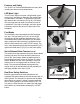
A
C
B
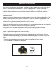
A
B
C
D
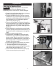
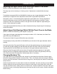
Adjusting the Blade Guides
Upper Guides: To adjust the upper blade guides,
rst position the roller guides relative to the blade by
loosening the Allen cap head screw (A-Fig.17) and
sliding the guide assembly until the side roller guides
are approximately 1/16” behind the gullet of the blade
then tighten the Allen cap head screw (A-Fig.17).
Next set the roller guides to within 1/32” of the blade
by releasing the lock knob (B-Fig.17) and turning
the micro-adjusting knob (C-Fig.17). Do not set the
guides too close, as this will adversely affect the life
of the blade. When the correct adjustment is reached,
lock the guides in position by tightening the lock knob
(B-Fig.17). Finally, follow the same steps above to
position the rear thrust roller guide.
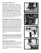
Lower Guides: To adjust the lower blade guides, rst
loosen the hex nut (A-Fig.18) then move the lower
guide support casting to allow the side roller guides to
be approximately 1/16” behind the gullets of the blade
and tighten the hex nut (A-Fig.18). Next set the roller
guides to within 1/32” of the blade by releasing the lock
knob (B-Fig.18) and turning the micro-adjusting knob
(C-Fig.18). Do not set the guides too close, as this will
adversely affect the life of the blade. When the correct
adjustment is reached, lock the guides in position by
tightening the lock knob (B-Fig.18). Adjust the thrust
bearing to be just clear of the back of the blade by
unlocking the hex nut (D-Fig.18), and turning adjusting
knob on rear of the trunnion. Finally, tighten hex nut
(D-Fig.18).
Make sure doors are closed, turn the bandsaw on and
inspect that the upper, lower and thrust bearings are
not turning. All bearings should not turn unless pressure
from workpiece is applied to the blade. If bearings are
turning under no pressure, repeat steps to adjust the
blade guides.
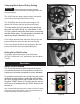
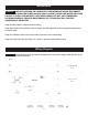
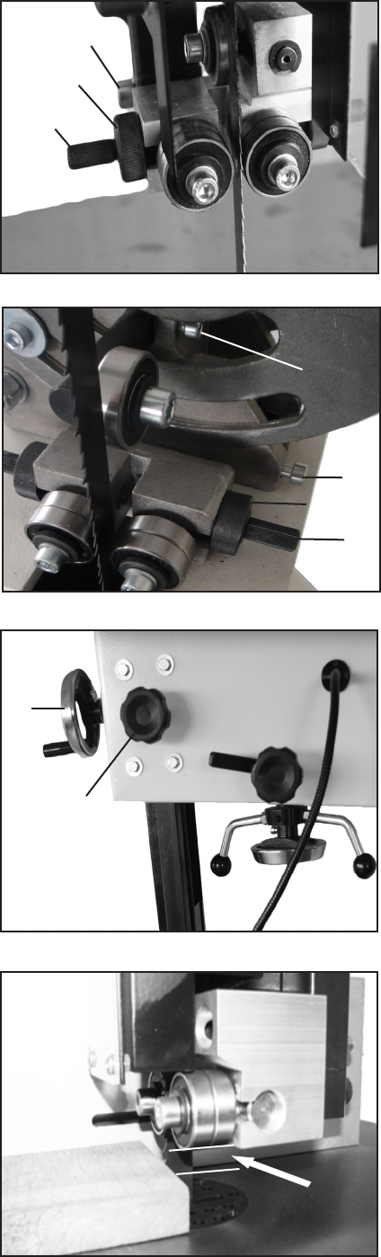
Adjusting the Cutting Height
Loosen the guidepost lock knob (A-Fig.19) and turn the
guidepost handwheel (B-Fig.19) to raise or lower the
guide post/upper blade guide assembly to the desired
height. Then tighten the guidepost lock knob.
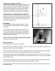
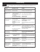
Note: The bottom edge of the guide bearings should
be approximately 1/4”above the top surface of the work
piece. (Fig.20)
Approximately
1/4”
B
A