0-305 10” Woodworking Bandsaw 4001824 Operator’s Manual Record the serial number and date of purchase in your manual for future reference. Serial Number: _________________________ Date of purchase: _________________________ For technical support or parts questions, email techsupport@rikontools.com or call toll free at (877)884-5167 10-305M4 www.rikontools.
TABLE OF CONTENTS Specifications.....................................................................................................................2 Safety Instructions ........................................................................................................3 - 6 Contents of Package ....................................................................................................7 Assembly ....................................................................................................
SAFETY INSTRUCTIONS IMPORTANT! Safety is the single most important consideration in the operation of this equipment. The following instructions must be followed at all times. Failure to follow all instructions listed below may result in electric shock, fire, and/or serious personal injury. There are certain applications for which this tool was designed. We strongly recommend that this tool not be modified and/ or used for any other application other than that for which it was designed.
SAFETY INSTRUCTIONS 12. KEEP PROTECTIVE GUARDS IN PLACE AND IN WORKING ORDER. 25. ALWAYS WEAR A DUST MASK TO PREVENT INHALING DANGEROUS DUST OR AIRBORNE PARTICLES, including wood dust, crystalline silica dust and asbestos dust. Direct particles away from face and body. Always operate tool in well ventilated area and provide for proper dust removal. Use dust collection system wherever possible.
SAFETY INSTRUCTIONS ELECTRICAL SAFETY EXTENSION CORDS THIS TOOL REQUIRES A 3-PRONG 110V RECEPTICAL, AND MUST BE GROUNDED WHILE IN USE TO PROTECT THE OPERATOR FROM ELECTRIC SHOCK. Keep the extension cord clear of the working area. Position the cord so that it will not get caught on lumber, tools or other obstructions while you are working with a power tool. Check extension cords before each use. If damaged replace immediately.
SAFETY INSTRUCTIONS SPECIFIC SAFETY INSTRUCTIONS FOR BAND SAWS 1. Always allow the bandsaw blade to stop before removing scrap pieces from table. 2. Always keep hands and fingers away from the blade. 3. Never attempt to saw stock that does not have a flat surface, unless a suitable support is used. 4. Always hold material firmly and feed it into the blade at a moderate speed. 5. Always turn off the machine if the material is to be backed out of an uncompleted cut. 6.
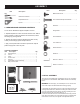
ASSEMBLY 1. TOOLS REQUIRED FOR ASSEMBLY LIST OF LOOSE PARTS IN BAG Item Description Qty Item Description Qty. Medium Screwdriver..............................1 Adjustable Wrench.................................1 Square ...................................................1 Blade Tension Knob.........................................1 Hex. Socket Head Cap Screw M6x30...............1 Washer 6.........................................................1 2.
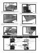
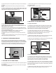
d. Place the blade tension knob on to the blade tensioner located at the top of the frame (See Fig. 4). Blade Tension Knob FIG. 1 FIG. 4 b. Fasten the guide rail with two each star knob screw and washer to the table. Use the hex socket head cap screw, washer and wing nut for correcting the working table flatness. (See Fig. 2) e. To ensure sufficient upright stability of the machine it should be bolted to floor, bench or worktable. For this purpose 6mm holes are provided in the machine’s base. (See Fig.
ADJUSTMENT 1. CENTERING THE TABLE 3. TILTING THE TABLE a. Loosen the four hex. bolts mounting the table to the upper table trunnion. (See Fig. 7) For bevel cuts, the table tilts 0 through 45 degrees. a. To tilt the table, loosen the wing nut on the table trunnion, set the table to the required angle and tighten the wing nut again (Fig. 10). Hex. bolt FIG. 7 Wing nut b. Move the table sideways as required, until the saw blade runs through the center of the table insert. c.
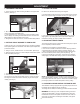
a. Remove the rip fence, the guide rail, the wing nut and screw from the table. b. Open the upper and lower doors by turning the door locking knobs. c. Loosen the blade tension by turning the blade tension knob on the top of the upper wheel housing counterclockwise until the saw blade has slackened (viewed from above) (See Fig. 12). c. Set the blade guide to the required height by turning the guide post adjusting knob. d. Tighten the wing nut after setting. Guide post adjusting knob Wing nut FIG. 14 8.
d. When the correct adjustment is reached, lock the rear roller guide in position with the guide adjusting screw. (D) Fig.16 Lock nut Hex. socket head cap screw Guide adjusting screw (C) FIG. 17 Guide adjusting screw (D) c. Tension the drive belt until there is 3/8” to 1/2” of deflection. d. Follow procedures for CHANGING AND ADJUSTING THE SAW BLADE & TRACKING THE BANDSAW BLADE, before restoring power to the bandsaw and setting up for use. FIG. 16 9. CHANGING THE DRIVE BELT TENSION a.
ELECTRICAL SCHEMATIC WARNING: This machine must be grounded. To avoid electrocution or fire, any repairs to electrical system should be done only by a qualified electrician, using genuine replacement parts. TROUBLESHOOTING Problem Diagnosis Remedy The machine does not work when switched on. 1. No power supply. 2. Defective switch. 3 Defective motor. 1. Check the cable for breakage. 2. Replace the lock switch. 3. Defective motor. The saw blade does not move with the motor running. 1.
TROUBLESHOOTING CHANGING THE MOTOR DRIVE BELT (Refer to parts diagram on page 16) Before changing the belt, make sure that the bandsaw is unplugged from the power source. Release the saw blade tension from the drive belt by turning the tension knob (Part #16) counter clockwise on top of the saw. Release the drive belt tension by loosening the Hex. Socket Head Cap Screw M8x30 (Part #125) on the motor located at the rear of the saw. .
TROUBLESHOOTING LOWER WHEEL ADJUSTMENTS The following instructions will correct common blade issues related to the lower wheel’s alignment in relation to the upper wheel. These adjustments will correct the blade position on the lower wheel and blade oscillation (wobble). These are critical adjustments which affect the performance and accuracy of the bandsaw. PLEASE READ AND UNDERSTAND THESE STEPS THOROUGHLY BEFORE MAKING ANY ADJUSTMENTS. FAILURE TO DO SO COULD DAMAGE THE MACHINE.
TROUBLESHOOTING If a blade is tracking on the rear of the lower wheel, away from the door, follow these steps: 1.) 2.) 3.) 4.) 5.) 6.) 7.) De-tension the saw blade. Loosen 9 o’clock shaft bolt to take pressure off the shaft. Loosen 6 o’clock shaft bolt one half rotation. Tighten the 12 o’clock shaft bolt until the shaft touches the 6 o’clock adjusting bolt. Lock all three shaft bolts. Re-tension the saw blade and set the upper wheel to plumb by adjusting the tracking knob.
PARTS DIAGRAM 16
PARTS LIST KEY NO. 9 10 15 16 17 18 19 20 21 22 23 24 25 26 27 28 29 30 31 32 33 34 35 36 37 38 39 40 41 42 43 44 45 46 47 DESCRIPTION MFG. PART NO. Rivet 4x8 Leaf Spring Blade Tension Knob Cap Blade Tension Knob Body Blade Tensioner Washer 8 Flange Nut M6 Carriage Bolt M8x50 Bushing Ring Top Plug Frame Hex. Bolt M6x12 Lock Nut M6 Washer 6 Gear Special Spring Washer 8 Tube Plastic Nut M20 Adjusting Knob Body Adjusting Knob Cap Blade Tracking Knob Cap Blade Tracking Knob Body Hex. Bolt M6x60 Hex.
PARTS DIAGRAM 18
PARTS LIST KEY NO. 83 84 85 86 87 88 89 90 91 92 98 99 100 101 102 103 104 105 106 107 108 109 110 115 116 117 125 126 127 128 128A 129 130 131 132 133 134 DESCRIPTION MFG. PART NO. Flat Countersunk Scr M6x10 Rod Guide Guide Rail Fence Carrier Special Screw Washer 10 Fence Handle Roll Pin 3x18 Star knob screw Washer 6 Bearing Mount Cylinder Hex. Socket Set Screw M6x10 Lower Guide Body Lower Guide Shaft Lower Guide Mount Lock Nut M6 Washer 6 Washer 6 Hex.
NOTES Use this section to record maintenance, service and any calls to Technical Support.
ACCESSORIES 13-913 10” Bandsaw Stand 13-920 Miter Gauge C10-393 Table Insert (4pk) Bandsaw Blades Where to buy: Contact RIKON at 877-884-5167 or info@rikontools.com.
10-305 For more information: 16 Progress Rd Billerica, MA 01821 877-884-5167 / 978-528-5380 techsupport@rikontools.com 10-305M4 www.rikontools.