2” Deluxe Woodworking Bandsaw Owner’s Manual Model: 10-315 Record the serial number and date of purchase in your manual for future reference. Serial number: Date of purchase: For more information: www.rikontools.com or info@rikontools.com For Parts or Questions: Part #10-315M1 techsupport@rikontools.
Operator Safety: Required Reading IMPORTANT! Safety is the single most important consideration in the operation of this equipment. The following instructions must be followed at all times. There are certain applications for which this tool was designed. We strongly recommend that this tool not be modified and/ or used for any other application other than that for which it was designed. If you have any questions about its application, do not use the tool until you have contacted us and we have advised you.
ALWAYS DISCONNECT TOOLS. Disconnect tools before servicing and when changing accessories such as blades, bits, and cutters. ALWAYS AVOID ACCIDENTAL STARTING. Make sure switch is in “OFF” position before plugging in cord. NEVER LEAVE TOOLS RUNNING UNATTENDED. ALWAYS CHECK FOR DAMAGED PARTS. Before initial or continual use of the tool, a guard or other part that is damaged should be checked to assure that it will operate properly and perform its intended function.
Table of Contents Safety Warnings..................................................................................................................................2 -3 Bandsaw Safety Rules ..........................................................................................................................3 Specifications ........................................................................................................................................4 Contents of Package .........................
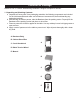
Contents of Package Model 10-315 12” Deluxe Woodworking Bandsaw is shipped complete in one box. 1. Unpacking and Checking Contents a. Separate all “loose parts” from packaging materials, the following components are included for the initial assemble and make sure all items are accounted for, before discarding any packaging material. b. With the help of another person, take the Bandsaw from the packing carton. Properly lift the Bandsaw off the packing carton and place on level floor. c.
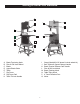
Contents of Package Cont. Table assembly: A. Table B. Table leveling bar and hardware C. 90° table stop bolt D. Table mounting bolts and washers D C A B Rip fence assembly: A. Scale B. Fence bar C. Fence D. Resaw bar E. Fence carrier F. Fence support on left side of the table G.Lock shoe A B C Tool holder assembly: A. L wrench 3MM B. L wrench 4MM C. L wrench 5MM D. L wrench 6MM E. Tool holder F.
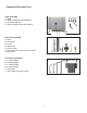
Getting to Know Your Bandsaw A L B K M C D E F N G H I Q J P A B C D E F G H Blade Tensioning Knob Rise & Fall Hand Wheel Blade Upper Blade Guide Table Rip Fence Rip Fence Rail Table Tilt Lock Handle I J K L M N P Q 7 Stand (Model#10-315 doesn’t include wheel kit) Belt Tension & Speed Change Handle Blade Tension Release Cam Handle Rise & Fall Lock Knob Blade Tracking Knob Table Tilting Knob 4” Dust Extraction Port Motor
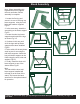
Stand Assembly Note: When assembling this legstand do not fully tighten the nuts and bolts until the assembly is complete. Fig.1S Fig.5S LONG MID BRACE SUPPORT 1. Locate the first leg and secure it to one of the long top brace supports using the nuts, bolts and washers supplied Fig.1S. 2. In the same way, attach the second leg to the brace support Fig.2S. Fig.2S 3. Locate the short top brace supports and install to the legs as shown Fig.3.S. FRONT LONG TOP BRACE SUPPORT 4.
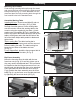
Assembly Mounting Top to Stand Feed the long mounting bolts up through the stand and secure the four corners using the washers and bolts provided (A-Fig.1). Lift the bandsaw over the stand and place the long mounting bolts through the four location holes in the bandsaw base. Assemble Working Table Installing 90°stop: Thread screw (M8x25) and nut (M8) to the bottom of the table. (A-Fig.2) With the help of another person, lift the working table onto the trunnion.
Installing the Tool Holder Assemble the tool holder to the column of the bandsaw with two pan head screws. Locate the two pan head screws from the bag of loose parts. Mount the tool holder to the column and install a pan head screw in each hole, then tighten with a Phillips screw driver. (Fig. 6) Assemble Hand-Wheels Attach the crank handle (Fig. 7) to the rack and pinion shaft on the upper part of the bandsaw, using the 5mm “L” wrench provided.
Tilting the Table Loosen the lock handle (A-Fig. 9) on the table trunnion. Turn the table tilting knob (B-Fig. 9) to adjust the table to the desired angle. Use the angle indicator scale on the trunnion bracket to find the desired angle. Retighten the lock handle to secure the table. A B Figure 9 Tracking the Saw Blade WARNING! Unplug the Bandsaw.
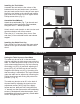
Adjustment Cont. b. Set both bearing guides to within 1/32” of the saw blade by releasing the guide adjusting screws (B-Fig.12) on each side of the saw blade, then by turning the micro-adjusting knobs(CFig.12). Do not set the bearing guides too close as this will adversely affect the life of the saw blade. A c. Adjust the rear bearing guide to be just clear of the back of the saw blade releasing the guide adjusting screw (A-Fig.13) and by turning the micro-adjusting knob (B-Fig.13). C B Figure 12 d.
Adjustment Cont. Adjusting the Rip Fence/Drift Align the fence assembly in or out until parallel with the side of the blade by turning the adjustment collars and the fence bolts accordingly(A-Fig.15). If the mounting bolts have been tightened, these will need loosened off before this adjustment can be made. The same adjustment can be made to compensate for blade drift. A Movement Check that the fence is 90 degrees to the table using a suitable square.
Changing the Blade Speed / Belt Tension warning! Before changing the speed, always WARNING! make sure the machine has been unplugged from the electrical supply. A This Bandsaw has two blade speeds, low speed (1445 ft/min) and high speed (2950 ft/min). The lower wheel has two integral “multi-vee” form pulleys, and the motor shaft has a twin multi-vee form pulley. The “multi-vee” belt passes around the wheel pulley and the motor pulley. The belt tension is released and applied by using the handwheel (A-Fig.
Replacing the Bandsaw Blade Cont. f) Re-tension the new blade by moving the quick release lever (A-Fig.21 on page 14) right to left and check the blade tracking. The blade should run in the center of the wheel. Refer to “Tracking the Saw Blade” on page 11 for more details. g) Reset the blade guides as described in the section “Adjusting the Blade Guides” on pages 11 and 12. h) Reset the blade tension as described in the section “Adjusting the Blade Tension” on page 11.
Maintenance Caution! BEFORE CLEANING OR CARRYING OUT MAINTENANCE WORK, DISCONNECT THE MACHINE FROM THE POWER SOURCE (WALL SOCKET). NEVER USE WATER OR OTHER LIQUIDS TO CLEAN THE MACHINE. USE A BRUSH. REGULAR MAINTENANCE OF THE MACHINE WILL PREVENT UNNECESSARY PROBLEMS. Keep the table clean to ensure accurate cutting. Keep the outside of the machine clean to ensure accurate operation of all moving parts and prevent excessive wear. Keep the ventilation slots of the motor clean to prevent it from overheating.
Troubleshooting warning! FOR YOUR OWN SAFETY, ALWAYS TURN OFF AND UNPLUG THE MACHINE BEFORE CARRYING OUT ANY TROUBLESHOOTING. TROUBLE REMEDY PROBABLE CAUSE The machine does not 1. No power supply. work when switched on. 2. Defective switch. Check the cable for breakage. Contact your local dealer for repair parts. The blade does not move with the motor running. 1. The quick release lever or blade tension handwheel has not been tightened. 2. The blade has come off one of the wheels. 3.
Troubleshooting Adjusting the Upper Blade Guide Bearings Parallel to the Blade (Refer to page 19 parts diagram) This step may not be necessary, it is factory preset. If adjustment is needed follow the steps below. First slightly loosen part #137 (4 each) cap screw on rear of upper Bandsaw housing (see page 19 in parts diagram). This will allow you to adjust the micro adjustment screws on part #143 (Guide Bracket). Next place a 3mm “L” wrench through one of the holes in part #139 (Guide Bracket Cover).
20 Parts Diagram 19
Parts Diagram Cont.
Parts Diagram Cont. 11. Diagrams & Components Stand 8 7 6 Ref No. Description 5 4 9 10 3 12 1 2 3 4 5 6 7 8 9 10 11 12 Rubber shoe Short mid brace support Leg Long top brace support Hex nut Washer Hex bolt Hex nut Washer Hex bolt Long mid brace support Short top brace support Ref No.
12. Parts List Parts List Ref No. Description Ref No. Description 4 5 6 7 8 9 10 11 12 13 14 15 16 17 18 19 20 21 22 23 24 25 26 27 29 30 31 32 33 34 35 36 38 39 40 42 44 45 46 47 48 49 50 51 54 55 56 57 58 59 60 Blade tension knob Frame Set screw M5-0.8x10 Safety switch Flat washer M5 Power cord Hex nut M8-1.
Ref No. 118 119 120 121 122 123 124 126 127 128 129 130 131 132 133 134 135 136 137 138 140 141 142 145 146 148 149 150 151 153 154 156 157 159 160 161 162 163 164 165 166 167 168 169 170 171 201 202 203 204 Description Lock handle Flat washer M5 Pointer Trunnion Guide post handwheel handle Hex nut Carriage bolt M6-1.0x65 Table Table insert Hex socket screw M6-1.
Warranty 2-Year Limited Warranty RIKON Power Tools/Richen Enterprise, Inc. (“Seller”) warrants to only the original retail consumer/purchaser of our products that each product be free from defects in materials and workmanship for a period of two (2) years from the date the product was purchased at retail. This warranty may not be transferred.
Notes 26
Notes 27
For more information: 16 Progress Rd. Billerica, MA 01821 877-884-5167/978-528-5380 techsupport@rikontools.com www.rikontools.com Copyright RIKON Power Tools, Inc.