8” Woodworking Bandsaw Owner’s Manual Model: 10-340 Record the serial number and date of purchase in your manual for future reference. Serial number: Date of purchase: For more information: www.rikontools.com Part #10-340M2 or info@rikontools.com For Parts or Questions: techsupport@rikontools.
Operator Safety: Required Reading IMPORTANT! Safety is the single most important consideration in the operation of this equipment. The following instructions must be followed at all times. There are certain applications for which this tool was designed. We strongly recommend that this tool not be modified and/or used for any other application other than that for which it was designed. If you have any questions about its application, do not use the tool until you have contacted us and we have advised you.
ALWAYS DISCONNECT TOOLS. Disconnect tools before servicing and when changing accessories such as blades, bits, and cutters. ALWAYS AVOID ACCIDENTAL STARTING. Make sure switch is in “OFF” position before plugging in cord. NEVER LEAVE TOOLS RUNNING UNATTENDED. ALWAYS CHECK FOR DAMAGED PARTS. Before initial or continual use of the tool, a guard or other part that is damaged should be checked to assure that it will operate properly and perform its intended function.
Table of Contents Safety Warnings..................................................................................................................................................2 -3 Bandsaw Safety Rules ..........................................................................................................................3 Specifications ........................................................................................................................................4 Contents of Package ..........
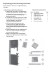
Unpacking and Checking Contents Model 10-340 18” Bandsaw is shipped complete in one box. 1. Unpacking and Checking Contents a. Separate all “loose parts” from packaging materials and check each item with “Table of Loose Parts” to make sure all items are accounted for, before discarding any packaging material. b. Thread hoist ring into threading hole on top of Bandsaw frame. This allows the user to connect a properly secured hoist mechanism to lift the Bandsaw. c.
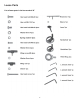
Loose Parts List of loose parts in the box marked “G” 6
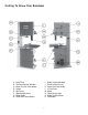
Getting To Know Your Bandsaw A. B. C. D. E. F. G. H. Hoist Ring Tension Indicator Window Blade Tension Hand-wheel Switch Rip Fence Speed Hand-wheel Blade Guide Guide Post Hand-Wheel I. J. K. L. M. N. O. P.
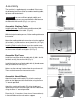
Assembly The machine is supplied partly assembled. Prior to use, the following items have to be assembled: working table, rip fence and hand-wheels. WARNING! To ensure sufficient upright stability and safety of this Bandsaw, you need to bolt the Bandsaw to the floor with M10 screws.(Fig 1) (not supplied) Assemble Working Table Installing 90°stop: Thread screw (m8x20) and nut (M81.25) to the bottom of the table. (Fig. 4A) Figure 1 With the help of another person, lift the working table onto the trunnion.
Adjustment Setting the Table Square to Saw Blade The table may be set at 90° to the saw blade sides by adjusting the table stop screw under the table. The table stop screw rests on the top of the quick release adjustment stop. By first loosening the locking nut (A--Fig. 5) and then adjusting the screw (B--Fig. 5), the table can be set correctly. Retighten the locking nut (A--Fig. 5) making sure that the setting is maintained.
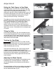
Adjusting the Blade Guides Upper Guides: To adjust the upper blade guides, first position the roller guides relative to the blade by loosening the locking hex screw (A--Fig. 9) and moving the guide carrier until the roller guides are approx. 1/16” behind the gullets of the blade. Next set the roller guides to within 1/32” of the blade by releasing the screw (B--Fig. 9) on each side of the blade. Do not set the guides too close, as this will adversely affect the life of the blade.
Changing the Blade Speed / Belt Tension WARNING! Before changing the speed, always make sure the machine has been unplugged from the electrical supply. This Bandsaw has two blade speeds, low speed (1510 ft/ min) and high speed (3220 ft/min). The lower wheel (A--Fig. 13) has two integral “V” form pulleys, and the motor shaft has a twin multi-vee form pulley (B--Fig. 13). The “V” belt (C--Fig. 13) passes around the wheel pulley and the motor pulley.
Re-sawing For re-sawing, attach the 3/8” x 3” post to the slot on the fence. Position the re-saw bar so that it is aligned with the front of the blade. The re-saw bar helps to correct any blade wandering during re-sawing operations. Operation The blade cuts on a continuous down-stroke. With both hands, firmly hold the workpiece down on the table, and feed it towards the blade slowly, keeping your hands away from the blade. For best results the blade must be sharp.
Troubleshooting WARNING! FOR YOUR OWN SAFETY, ALWAYS TURN OFF AND UNPLUG THE MACHINE BEFORE CARRYING OUT ANY TROUBLESHOOTING. TROUBLE PROBABLE CAUSE REMEDY The machine does not work when switched on. 1. No power supply. 2. Defective switch. Check the cable for breakage. Contact your local dealer for repair. The blade does not move 1. The quick release lever or with the motor running. blade tension handwheel has not been tightened. 2. The blade has come off one of the wheels. 3.
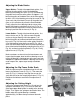
Troubleshooting Cont. Adjusting the Upper Blade Guide Bearings Parallel to the Blade (Refer to page 17 parts diagram) This step may not be necessary, it is factory preset. If adjustment is needed follow the steps below. First slightly loosen part #162 (4 each) cap screw on rear of upper Bandsaw housing (see page 17 in parts diagram) This will allow you to adjust the micro adjustment screws on part #164 (Guide Bracket). Next place a 3mm “L” wrench through one of the holes in part #169 (Guide Bracket Cover).
Parts Diagram 15
Parts Diagram Cont.
Parts List Part No. 3 4 5 6 7 8 9 10 11 12 13 14 15 16 17 18 19 20 21 22 23 24 25 26 27 28 29 30 31 32 33 34 35 36 37 38 39 40 41 42 43 44 45 46 47 48 49 50 Description Tube Ring Frame Set Screw M6-1.0x10 Switch Cord Flat Washer M5 Power Cord Hex Nut M6-1.0 Pointer Step Screw Upper Shaft Roll Pin 5x36 Upper Wheel Shaft Hinge Upper Wheel Shaft Bushing Bearing 6204 Upper Wheel Int Retaining Ring M47 Flat Washer M8 Hex Bolt M8-1.25x30 Saw Blade Board Hex Bolt M6-1.
100 101 102 103 104 105 106 107 108 109 110 111 112 113 114 115 116 117 118 119 120 121 122 123 124 125 126 127 128 130 131 134 135 136 137 138 140 141 142 143 144 145 146 148 149 150 151 152 153 154 156 157 158 159 160 161 162 163 164 165 166 167 168 169 170 171 176 201 202 203 204 205 206 207 208 209 210 211 212 213 214 215 216 217 220 221 222 223 224 225 226 227 228 229 230 231 232 233A 250 Small Gear Table Tilting Knob Trunnion Support Bracket Lock Washer 12 Flat Washer M10 Hex Bolt M6-1.
WARRANTY 2-Year Limited Warranty RIKON Power Tools/Richen Enterprise, Inc. (“Seller”) warrants to only the original retail consumer/purchaser of our products that each product be free from defects in materials and workmanship for a period of two (2) years from the date the product was purchased at retail. This warranty may not be transferred.
For more information: 400 West Cummings Park, Suite 1000 Woburn, MA 01801 877-884-5167/781-933-8400 techsupport@rikontools.com www.rikontools.com Copyright Richen Enterprise, Inc.