0-346 18” Professional Bandsaw 4001824 Operator’s Manual Record the serial number and date of purchase in your manual for future reference. Serial Number: _________________________ Date of purchase: _________________________ For technical support or parts questions, email techsupport@rikontools.com or call toll free at (877)884-5167 10-346M1 www.rikontools.
TABLE OF CONTENTS Specifications.....................................................................................................................2 Safety Instructions ........................................................................................................3 - 6 Getting To Know Your Machine .........................................................................................7 Contents of Package ...........................................................................................
SAFETY INSTRUCTIONS IMPORTANT! Safety is the single most important consideration in the operation of this equipment. The following instructions must be followed at all times. Failure to follow all instructions listed below may result in electric shock, fire, and/or serious personal injury. There are certain applications for which this tool was designed. We strongly recommend that this tool not be modified and/ or used for any other application other than that for which it was designed.
SAFETY INSTRUCTIONS 12. KEEP PROTECTIVE GUARDS IN PLACE AND IN WORKING ORDER. 25. ALWAYS WEAR A DUST MASK TO PREVENT INHALING DANGEROUS DUST OR AIRBORNE PARTICLES, including wood dust, crystalline silica dust and asbestos dust. Direct particles away from face and body. Always operate tool in well ventilated area and provide for proper dust removal. Use dust collection system wherever possible.
SAFETY INSTRUCTIONS ELECTRICAL SAFETY EXTENSION CORDS Keep the extension cord clear of the working area. Position the cord so that it will not get caught on lumber, tools or other obstructions while you are working with a power tool. THIS TOOL REQUIRES THE INSTALLATION OF A 220V PLUG (NOT INCLUDED), AND MUST BE GROUNDED WHILE IN USE TO PROTECT THE OPERATOR FROM ELECTRIC SHOCK. Check extension cords before each use. If damaged replace immediately.
SAFETY INSTRUCTIONS SPECIFIC SAFETY INSTRUCTIONS FOR BAND SAWS 1. Always allow the bandsaw blade to stop before removing scrap pieces from table. 2. Always keep hands and fingers away from the blade. 3. Never attempt to saw stock that does not have a flat surface, unless a suitable support is used. 4. Always hold material firmly and feed it into the blade at a moderate speed. 5. Always turn off the machine if the material is to be backed out of an uncompleted cut. 6.
GETTING TO KNOW YOUR MACHINE A F O B G C P H I D Q J R E S K L T M U N A. B. C. D. E. F. G. H. I. J. K. Hoist Ring Tension Indicator Window Blade Tension Hand Wheel Switch Rip Fence Blade Tracking Window Guide Post Lock Knob Guide Post Rise/Fall Handle Hinged Blade Guard Blade Guides Work Table L. M. N. O. P. Q. R. S. T. U.
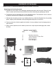
CONTENTS OF PACKAGE Model 10-346 18” Professional Bandsaw is shipped complete in one crate. Unpacking and Checking Contents a. Separate all “loose parts” from packaging materials and check each item with “Table of Loose Parts” to make sure all items are accounted for, before discarding any packaging material. b. Thread hoist ring into threading hole on top of Bandsaw frame. This allows the user to connect a properly secured hoist mechanism to lift the Bandsaw. c.
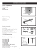
CONTENTS OF PACKAGE LIST OF LOOSE PARTS Table Assembly: A. Table B. Rip Fence Rail A B Rip Fence Assembly: A. Rip Fence B. Rip Fence Carrier C. Re-saw Bar A C B Bandsaw Accessories: A A. Hoist Ring* B. Hex Screw & Nut for Hanging Push Stick* C. Keys for ON/OFF Switch Lock D. Lower Door Blade Guard E. Hardware for Lower Door Blade Guard* F. Push Stick G. Dust Port 4” and Hardware * (If not pre-installed on saw) F Tools for Assembly & Adjustments: C D E G A A. Hex Wrench 3MM B. Hex Wrench 4MM C.
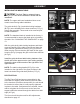
ASSEMBLY INSTALLING THE WORK TABLE The Work Table is extremely heavy. It may require two other individuals to assist with the installation. C A NOTE: The upper and lower bandwheel doors must remain closed during table installation. B The guide shaft (A-Fig.1) and table locking hardware (B-Fig.1) were installed on the lower trunnion (C-Fig.1) during saw assembly. These need to be removed prior to table installation. Figure 1 NOTE: The bandsaw blade is installed at the factory.
ASSEMBLY / ADJUSTMENTS INSTALLING THE 4” DUST PORT The 4” dust port under the table is installed on the frame above the lower door knob. Locate four 4mm pan head screws and four 4mm flat washers from the hardware pack. Using a Phillips-head screw driver install the screws through the dust port flange into pre-threaded holes in the frame. See Figure 5. INSTALLING THE LOWER DOOR BLADE GUARD Hardware for the lower door blade guard has been preinstalled at the factory.
ADJUSTMENTS TILTING THE TABLE Loosen the locking handle (A-Fig.9) on the table trunnion. Install the Table Tilting Wrench (B-Fig.9) onto the Gear Shaft (C-Fig.9). Turn the Table Tilting Wrench to adjust the table to the desired angle. Use the angle indicator scale on the trunnion bracket to find the desired angle. Retighten the lock handle to secure the table. C B A Figure 9 TRACKING THE BANDSAW BLADE A blade is provided and installed at the factory.
ADJUSTMENTS Always tension the blade with the quick release lever in the “On” position. Failure to do so could result in lack of blade tension or tension failure. BLADE TENSION INDICATOR ADJUSTMENT A The Blade Tension Indicator arrow should be checked and adjusted the first time the saw is set up and run, and whenever a new blade is installed. The blade tension indicator can also be adjusted for blades made from thicker steel, or cut over/under in length by different manufacturers.
ADJUSTMENTS Continued from Page 13 A f) Re-tension the new blade by moving the quick release lever (Fig.15) left to right and check the blade tracking. With your hand, slowly spin the upper wheel clockwise three times. The blade should run in the center of both wheels. Refer to “Tracking the Saw Blade” on page 12 for more details. Figure 17 g) Set the blade guides as described in the section “Adjusting the Blade Guides” below on this page.
ADJUSTMENTS When the correct adjustment is reached, lock the guides in position by re-tightening the lock knob (B-Fig.20). Adjust the thrust guide to be just clear of the back of the blade by unlocking the wing nut (C-Fig.20), and turning adjusting knob on rear of the trunnion. Finally, re-tighten the wing nut (C-Fig.20). B A Make sure the doors are closed, turn the bandsaw on and inspect that the upper, lower and thrust guides are not turning.
OPERATION BASIC OPERATION The blade cuts on a continuous down-stroke. Never start the saw with the workpiece in contact with the saw blade. With both hands, firmly hold the workpiece down on the table, and feed it slowly towards the blade, putting only light pressure on it, and keeping your hands away from the blade. Keep your hands/fingers away from the blade. Use a push stick whenever working close to the blade. For best results the blade must be sharp.
OPERATION RE-SAWING A re-saw guide bar is supplied to help correct any blade wandering during certain re-sawing operations. For re-sawing, attach the re-saw bar to the slot on the fence. Position the re-saw bar so that it is aligned with the front of the blade. Draw a reference line down the workpiece. Use the bar as a pivot point, angling the wood left or right while against the bar, to follow the line through the cut. Figure 27.
MAINTENANCE BEFORE CLEANING OR CARRYING OUT MAINTENANCE WORK, DISCONNECT THE MACHINE FROM THE POWER SOURCE (WALL SOCKET). NEVER USE WATER OR OTHER LIQUIDS TO CLEAN THE MACHINE. USE A BENCH BRUSH. DO NOT USE COMPRESSED AIR NEAR BEARINGS. REGULAR MAINTENANCE OF THE MACHINE WILL PREVENT UNNECESSARY PROBLEMS. 1. Keep the table clean to ensure accurate cutting. 2. Keep the outside of the machine clean to ensure accurate operation of all moving parts and prevent excessive wear. 3.
NOTES Use this section to record maintenance, service and any calls to Technical Support.
TROUBLESHOOTING FOR YOUR OWN SAFETY, ALWAYS TURN OFF AND UNPLUG THE MACHINE BEFORE CARRYING OUT ANY TROUBLESHOOTING. TROUBLE PROBABLE CAUSE REMEDY The machine does not 1. No power supply. work when switched on. 2. Defective switch. Check the cable for breakage. Contact your local dealer for repair. The blade does not move with the motor running. 1. The quick release lever or blade tension handwheel has not been tightened. 2. The blade has come off one of the wheels. 3. The saw blade has broken. 4.
TROUBLESHOOTING CHANGING THE MOTOR DRIVE BELT (Refer to “Frame Assembly” parts diagram on page 24 and “Wheel Assembly” parts diagram on page 26) Before changing the belt, make sure that the bandsaw is unplugged from the power source. Release the saw blade tension from the drive belt by turning the quick release blade tension lever. From the rear of the machine, loosen the two Hex Nuts (Part #54) that secure the motor to the frame. oosen the Hex Nut on the top of the Motor Adjusting Rod (Part #103).
TROUBLESHOOTING LOWER WHEEL ADJUSTMENTS The following instructions will correct common blade issues related to the lower wheel’s alignment in relation to the upper wheel. These adjustments will correct the blade position on the lower wheel and blade oscillation (wobble). These are critical adjustments which affect the performance and accuracy of the bandsaw. PLEASE READ AND UNDERSTAND THESE STEPS THOROUGHLY BEFORE MAKING ANY ADJUSTMENTS. FAILURE TO DO SO COULD DAMAGE THE MACHINE.
TROUBLESHOOTING If a blade is tracking on the rear of the lower wheel, away from the door, follow these steps: 1.) 2.) 3.) 4.) 5.) 6.) 7.) De-tension the saw blade. Loosen 9 o’clock shaft bolt to take pressure off the shaft. Loosen 6 o’clock shaft bolt one half rotation. Tighten the 12 o’clock shaft bolt until the shaft touches the 6 o’clock adjusting bolt. Lock all three shaft bolts. Re-tension the saw blade and set the upper wheel to plumb by adjusting the tracking knob.
PARTS DIAGRAM FRAME ASSEMBLY NOTE: Please reference the Manufacturer’s Part Number when calling for Replacement Parts. For Parts under Warranty, the serial number of your machine is required.
PARTS LIST FRAME ASSEMBLY KEY NO.
PARTS DIAGRAM WHEEL ASSEMBLY 26
PARTS LIST WHEEL ASSEMBLY KEY NO. DESCRIPTION QTY MFG. PART NO. 123 124 125 126 127 Hexagon Socket Cap Screw Washer Retaining Ring Deep Groove Ball Bearing Upper Wheel 2 2 4 4 1 10-346-123 10-346-124 10-346-125 10-346-126 10-346-127 128 129 130 131 Tube Tire Blade Lower Wheel 2 2 1 1 10-346-128 10-346-129 10-346-130 10-346-131 NOTE: Please reference the Manufacturer’s Part Number when calling for Replacement Parts. For Parts under Warranty, the serial number of your machine is required.
PARTS DIAGRAM TABLE ASSEMBLY 28
PARTS LIST TABLE ASSEMBLY KEY NO. DESCRIPTION 132 133 134 135 136 137 138 139 140 141 142 143 144 145 146 147 148 149 150 151 152 153 154 155 156 157 158 159 160 161 162 163 164 165 QTY MFG. PART NO.
PARTS DIAGRAM BLADE TENSION & TRACKING 30
PARTS LIST BLADE TENSIONING & TRACKING KEY NO.
PARTS DIAGRAM GUIDE POST ASSEMBLY NOTE: Please reference the Manufacturer’s Part Number when calling for Replacement Parts. For Parts under Warranty, the serial number of your machine is required.
PARTS LIST GUIDE POST ASSEMBLY KEY NO. DESCRIPTION 200 201 202 203 204 205 206 207 208 209 210 211 212 QTY Retaining Ring Rack Blade Guard Nut Flat Washer Clear Window Pan Head Screw Nut Hexagon Socket Cap Screw Flat Washer Upper Guide Base Hexagon Socket Cap Screw Connection Block 33 1 1 1 1 1 1 4 4 2 2 1 1 1 MFG. PART NO.
PARTS DIAGRAM FENCE ASSEMBLY NOTE: Please reference the Manufacturer’s Part Number when calling for Replacement Parts. For Parts under Warranty, the serial number of your machine is required.
PARTS LIST FENCE ASSEMBLY KEY NO. DESCRIPTION 213 214 215 216 217 218 219 220 221 222 223 224 225 226 227 228 QTY Plate Fence Carrier Handle Washer Hexagon Socket Cap Screw Fence Rail Joint Lever Nut Flat Washer Hex Nut Stop Lever Bolt Double-end Bolt Washer Adjustable Handle Fence 35 1 1 1 2 2 1 2 2 4 2 1 1 1 1 1 1 MFG. PART NO.
WARRANTY WARRANTY 37
10-346 For more information: 16 Progress Rd Billerica, MA 01821 877-884-5167 / 978-528-5380 techsupport@rikontools.com 10-346M1 www.rikontools.