8” Wood/Metal Bandsaw Owner’s Manual Model: 10-370 Record the serial number and date of purchase in your manual for future reference. Serial number: Date of purchase: For more information: www.rikontools.com or info@rikontools.com For Parts or Questions: Part #10-370M1 techsupport@rikontools.
Operator Safety: Required Reading IMPORTANT! Safety is the single most important consideration in the operation of this equipment. The following instructions must be followed at all times. There are certain applications for which this tool was designed. We strongly recommend that this tool not be modified and/ or used for any other application other than that for which it was designed. If you have any questions about its application, do not use the tool until you have contacted us and we have advised you.
ALWAYS DISCONNECT TOOLS. Disconnect tools before servicing and when changing accessories such as blades, bits, and cutters. ALWAYS AVOID ACCIDENTAL STARTING. Make sure switch is in “OFF” position before plugging in cord. NEVER LEAVE TOOLS RUNNING UNATTENDED. ALWAYS CHECK FOR DAMAGED PARTS. Before initial or continual use of the tool, a guard or other part that is damaged should be checked to assure that it will operate properly and perform its intended function.
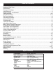
Table of Contents Safety Warnings..................................................................................................................................................2 -3 Bandsaw Safety Rules ..........................................................................................................................3 Specifications ........................................................................................................................................4 Contents of Package ..........
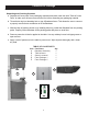
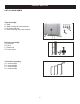
Contents of Package Model 10-370 18” Wood/Metal Bandsaw is shipped complete in one box. Unpacking and Checking Contents a. Separate all “loose parts” from packaging materials and check each item with “Table of Loose Parts” to make sure all items are accounted for, before discarding any packaging material. b. Thread hoist ring into threading hole on top of Bandsaw frame. This allows the user to connect a properly secured hoist mechanism to lift the Bandsaw. c.
Loose Parts List LIST OF LOOSE PARTS Table assembly: A. Table B. Table leveling bar and hardware C. 90° table stop bolt D. Table mounting bolts and washers D C A B Rip fence assembly: A. Fence bar B. Fence C. Resaw bar D. Fence carrier A D C B Tool holder assembly: A. L wrench 3MM B. L wrench 4MM C. L wrench 5MM D.
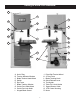
Getting to Know Your Bandsaw A F L B G M C H D N I O E P A. B. C. D. E. F. G. H. I. J Q K R Hoist Ring Tension Indicator Window Blade Tension Hand-Wheel Switch Rip Fence Blade Tracking Window Guide Post Hand-Wheel Guide Post Lock Knob Hinged Blade Guard J. K. L. M. N. O. P. Q. R.
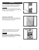
Assembly The 10-370 Bandsaw is supplied partly assembled. Prior to use, the following items have to be assembled: switch, working table, rip fence and hand-wheels. Warning! To ensure sufficient upright stability and safety of this bandsaw, you need to bolt the bandsaw to the floor with M10 screws.(Fig 1) (not supplied). Mounting Holes Figure 1 Installing the Switch Box Remove the two screws that were pre-installed on the bandsaw column (A-Fig.2).
Assembly Installing the Switch Box Cont. Mount the switch by using the corresponding holes (A-Fig.5) in the back of the switch box. Use screws that were removed from the frame shown in Fig.3. to mount switch box to the column. Next, install the control panel to the switch box. Make sure that wires in the switch box do not become cut or pinched while intalling the control panel. Tighten the four control panels screws (A-Fig.6) with a flat-head screw driver.
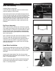
Assembly Blade Slot Work Table Assembly Installing Table Leveling Bar: Locate the table leveling bar, two hex socket screws and two washers (A-Fig.9 Inset). Insert a hex socket screw and washer through the left hole of the table leveling bar and into the threaded hole on the left side of the blade slot (B-Fig.9). Make sure that the opening of the slot on the right side of the table leveling bar faces toward the table trunnion. This will allow the table leveling bar to open outward from the bandsaw.
Assembly Storage for the “L” wrenches is provided for quick access when adjustments are needed. Tool Holder Place the (4) “L” wrenches (3mm, 4mm, 5mm and 6mm) in the tool holder on the rear column support (Fig.13). Adjustments Setting the Table Square to Saw Blade The table may be set at 90° to the saw blade sides by adjusting the table stop screw under the table. The table stop screw rests on the top of the quick release adjustment stop. By first loosening the locking nut (A-Fig.
Adjustments A Tracking the Saw Blade B Warning! Unplug the bandsaw. Make sure the upper and lower blade guides are adjusted away from the blade and the tension scale is set to correspond to the width of the blade you are using. Note: The blade tension scale may read differently due to cut specifications of the blade manufacturer. It might be necessary to increase/decrease tension up/down one size on blade tension scale to achieve proper blade tension. Figure 17 Open both doors.
Adjustments Changing the Bandsaw Blade A Warning! Unplug the machine from the electrical supply. This ensures that the Bandsaw will not accidentally turn on if the ON/OFF switch is bumped. a) Open the top and bottom wheel doors by turning the door locking knobs. (A-Fig.21) b) Release the blade tension by moving the quick release lever (A-Fig.22) from right to left. Open the hinged door on the blade guard by loosening the hex screw (A-Fig. 23). Loosen then open the table leveling bar (A-Fig. 24).
Adjusting the Blade Guides Upper Guides: To adjust the upper blade guides, first position the roller guides relative to the blade by loosening the locking hex screw (A-Fig.25) and moving the guide carrier until the roller guides are approximately 1/16” behind the gullets of the Bandsaw blade and tighten the hex nut (A-Fig.25). Next set the roller guides to within 1/32” of the blade by releasing the screw (B-Fig.25) on each side of the blade.
Changing Blade Speed Pulley Setting Warning! Before changing the speed, always make sure the machine has been unplugged from the electrical supply. The 10-370 has two pulley speed ranges, low speed (82-1312 ft/min) and high speed (328-3280 ft/min). The lower wheel (A-Fig.29) has two integral “V” form pulleys, and the motor shaft has a twin multi-vee form pulley (B-Fig.29). The “V” belt (C-Fig.29) passes around the wheel pulley and the motor pulley.
Adjusting the Rip Fence/Drift Align the fence assembly in or out until parallel with the side of the blade by turning the adjustment collars and the fence bolts accordingly (A-Fig.31). If the mounting bolts have been tightened, these will need loosened off before this adjustment can be made. The same adjustment can be made to compensate for blade drift. A Check that the fence is 90 degrees to the table using a suitable square. If no adjustments are needed fully tighten the fence bar nuts.
Metal Cutting Warning! The 10-370 Wood/Metal bandsaw is designed for dry cutting only. Do not us lubricants/ coolants with this bandsaw. Proper blade selection for the material to be cut is key to good performance. Do not force the material into the blade as excessive heat will lead to premature blade failure. Poor cutting results will also occur. Always keep three teeth in the cut. Stack or bundle cutting is not recommended with this bandsaw.
Electrical Requirements In the event of a malfunction or breakdown, grounding provides a path of least resistance for electric current to reduce the risk of electric shock. This tool is equipped with an electric cord having an equipment-grounding conductor and a grounding plug. The plug must be plugged into a matching outlet that is properly installed and grounded in accordance with all local codes and ordinances. Do not modify the plug provided.
Maintenance Caution! BEFORE CLEANING OR CARRYING OUT MAINTENANCE WORK, DISCONNECT THE MACHINE FROM THE POWER SOURCE (WALL SOCKET). NEVER USE WATER OR OTHER LIQUIDS TO CLEAN THE MACHINE. USE A BENCH BRUSH. DO NOT USE COMPRESSED AIR NEAR BEARINGS. REGULAR MAINTENANCE OF THE MACHINE WILL PREVENT UNNECESSARY PROBLEMS. Keep the table clean to ensure accurate cutting. Keep the outside of the machine clean to ensure accurate operation of all moving parts and prevent excessive wear.
Troubleshooting WARNING! FOR YOUR OWN SAFETY, ALWAYS TURN OFF AND UNPLUG THE MACHINE BEFORE CARRYING OUT ANY TROUBLESHOOTING. TROUBLE PROBABLE CAUSE REMEDY The machine does not 1. No power supply. work when switched on. 2. Defective switch. Check the cable for breakage. Contact your local dealer for repair. The blade does not move with the motor running. 1. The quick release lever or blade tension handwheel has not been tightened. 2. The blade has come off one of the wheels. 3.
Troubleshooting Adjusting the Upper Blade Guide Bearings Parallel to the Blade (Reference Guide Assembly parts diagram on page 26) This step may not be necessary, it is factory preset. If adjustment is needed follow the steps below. First slightly loosen part #23C Screw M8X16 (4 each) on rear of upper bandsaw housing. This will allow you to adjust the micro adjustment screws on part #21C (Guide Bracket). Next place a 3mm “L” wrench through one of the holes in part #16C (Cover).
Parts Diagram Frame Assembly (A) 22
Parts List Frame Assembly(A) Key No. 1A 2A 3A 4A 5A 6A 7A 8A 9A 10A 11A 12A 13A 14A 15A 16A 17A 18A 19A 20A 21A 22A 23A 24A 25A 26A Part No.
Parts Diagram Table Assembly (B) 24
Parts List Table Assembly (B) Key No. 1B 2B 3B 4B 5B 6B 7B 8B 9B 10B 11B 12B 13B 14B 15B 16B 17B 18B 19B 20B 21B 22B 23B 24B 25B 26B 27B 28B 29B 30B 31B 32B Part No.
Parts Diagram Guide Assembly (C) 26
Parts List Guide Assembly (C) Key No. 1C 2C 3C 4C 5C 6C 7C 8C 9C 10C 11C 12C 13C 14C 15C 16C 17C 18C 19C 20C 21C 22C 23C 24C 25C 26C 27C 28C 29C 30C 31C 32C 33C 34C Part No.
Parts Diagram Blade Tension/Tracking (D) 28
Parts List Blade Tension/Tracking (D) Key No. 1D 2D 3D 4D 5D 6D 7D 8D 9D 10D 11D 12D 13D 14D 15D 16D 17D 18D 19D 20D 21D 22D 23D 24D 25D 26D 27D 28D Part No.
Parts Diagram Drive Assembly (E) 30
Parts List Drive Assembly (E) Key No. 1E 2E 3E 4E 5E 6E 7E 8E 9E 10E 11E 12E 13E 14E 15E 16E 17E 18E 19E 20E 21E 22E 23E 24E 25E 26E 27E 28E 29E 30E 31E Part No.
Warranty 5-Year Limited Warranty RIKON Power Tools Inc. (“Seller”) warrants to only the original retail consumer/purchaser of our products that each product be free from defects in materials and workmanship for a period of five (5) years from the date the product was purchased at retail. This warranty may not be transferred. This warranty does not apply to defects due directly or indirectly to misuse, abuse, negligence, accidents, repairs, alterations, lack of maintenance or normal wear and tear.
For more information: 16 Progress Road Billerica, MA 01821 877-884-5167/978-528-5380 techsupport@rikontools.com www.rikontools.com Copyright RIKON Power Tools, Inc.