6” Jointer with Center Mount Fence Owner’s Manual Model: 20-100 Record the serial number and date of purchase in your manual for future reference. Serial number: Date of purchase: For more information: www.rikontools.com or info@rikontools.com For Parts or Questions: techsupport@rikontools.
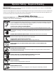
Operator Safety: Required Reading IMPORTANT! Safety is the single most important consideration in the operation of this equipment. The following instructions must be followed at all times. There are certain applications for which this tool was designed. We strongly recommend that this tool not be modified and/or used for any other application other than that for which it was designed. If you have any questions about its application, do not use the tool until you have contacted us and we have advised you.
ALWAYS DISCONNECT TOOLS. Disconnect tools before servicing and when changing accessories such as blades, bits, and cutters. ALWAYS AVOID ACCIDENTAL STARTING. Make sure switch is in “OFF” position before plugging in cord. NEVER LEAVE TOOLS RUNNING UNATTENDED. ALWAYS CHECK FOR DAMAGED PARTS. Before initial or continual use of the tool, a guard or other part that is damaged should be checked to assure that it will operate properly and perform its intended function.
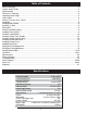
Table of Contents Safety Warnings....................................................................................................................................2 Jointer Safety Rules ..........................................................................................................................3 Specifications ........................................................................................................................................4 Contents of Package ...........................
Unpacking and Checking Contents The 20-100 RIKON 6” Jointer is shipped in two cartons.
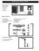
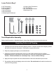
Loose Parts in Bag 2 3 3/8” Flat Washers 3 3/8” Lock Washers 3 Mounting Bolts 1 3mm Hex Wrench 1 5mm Hex Wrench 1 8/10mm Open End Wrench 1 12/14mm Open End Wrench 2 1/8” Flat Washers 6 1/8”x3/8” Pan Head Screws 1 Blade Adjust Tool Tools Required for Assembly Philips Head Screwdriver, Adjustable Wrench, 14mm Open End Wrench and a metric socket set. Unpacking Carton and Cleaning 1. Carefully remove all contents from both shipping cartons.
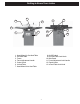
Getting to Know Your Jointer 5 3 4 6 11 2 13 7 1 8 1. 2. 3. 4. 5. 6. 7. 12 9 10 8. On/Off Switch 9. Out-feed Table Lock Knob 10. Belt Guard 11. Fence Adjustment Lock Handle 12. Depth Limiter 13.
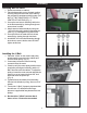
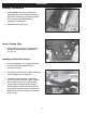
Assembly Installing Bed to Stand 1. Remove rear door on cabinet. 2. Place bed assembly on top of stand, making sure the pulleys face the rear of the cabinet. Ask a friend for assistance with this step. (DO NOT LIFT BY TABLE ENDS, LIFT FROM CENTER OF CASTING) (Fig. 1) 3. Line up the two holes in stand top with holes in the bed assembly by viewing through rear access door in stand. 4. Attach stand to bed assembly by using two 3/8" lock bolts spring washers and washers. (See Fig.
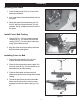
Assembly Installing Belt Guard 1. Place the belt guard (A-Fig. 6) over the belt opening in the stand. 2. Line up the holes in the stand with the holes in the guard. A 3. Attach the guard to the stand using two 1/420x1/2" pan head screws and two 1/4" lock washers. (B-Fig. 6) Make sure belt is clear of the guard. B Figure 6 Install Fence Bed Casting B 1. Use two 3/8" x 1-1/2" hex socket bolts and washers (A-Fig. 7) to attach the fence bed casting (B-Fig.
Assembly Installing Handwheels A 1. Press handwheels (A-Fig. 9) onto shaft, aligning the slot in the handle with the pin on the shaft. If necessary, use a hammer with a block of wood to tap the handwheel completely onto the shaft. B 2. Tighten set screw, (B-Fig. 9). Figure 9 Depth Limiting Stop 1. Attach depth limiting stop. Thread stop into steel plate at the rear of the infeed table. (A- Fig. 10) A Installing Cutter-Head Guard Figure 10 1. Turn spring knob (A-Fig.
Assembly Installing Access Cover 1. Install access cover by placing bottom of panel into access in stand and fasten by turning latch knob. (Figure 12) Figure 12 Installing Dust Chute 1. Attach the dust chute (Figure 13) to the base with four 1/4"-10x1/2"pan head screws and four washers. Figure 13 Adjustments 90º Fence Adjustment AA 1. Set in-feed table to the same height as the outfeed table. 2. Move the fence by releasing lock handle (A-Fig.
Adjustments 4. Place a combination square on the in-feed table to check that the fence is 90º to the table. (A-Fig. 15) 5. If fence is not square to table, release lock handle (A-Fig. 16) and adjust using handle (C-Fig. 16) until the fence is 90º. 6. Now that the fence is 90º to the table, adjust the positive stop screw assembly (E-Fig. 16) to maintain the 90º position. A 7. Retighten lock handle (A-Fig. 16). Figure 15 45º Fence Adjustment C E F G 1. Loosen lock handle (A-Fig. 16).
Adjustments Setting Out-feed Table to Cutterhead Knives WARNING! DO NOT connect machine to power source at this time! Cutterhead blades are extremely sharp! Use Caution when hands are near the cutter-head! Failure to comply may cause serious injury! 1. Unplug the Jointer from the power source. 2. Remove the blade guard by turning knob. (Fig. 18) clockwise while lifting up on the blade guard. Caution: Blades are sharp! Use care while working around the blades. 3.
Adjustments 7. If blade is higher or lower at the right of the table than it is at the left, slightly loosen the four locking screws (A-Fig. 22) by turning clockwise as viewed from the in-feed table. To lower, turn the jack screws clockwise. To raise the blade , turn the jack screws counterclockwise. Blades are set at the proper height when the top of the blades are 1/16" above the cutter-head. Alternately tighten four locking screws to hold each blade in place. A 8.
Operation Fence Operation The fence can be moved forward or backward across the width of the table (B-Fig. 24). It also tilts up to 45 degrees forward and backward with a positive stop at 90 degrees. A To slide fence forward or backward: When edge jointing, the fence assembly should periodically be moved to different positions to distribute wear on the cutterhead knives. 1. Loosen the locking handle (A-Fig. 24). 2. Push the entire fence assembly (B-Fig.
Operation Important: If you are inexperienced at jointing, use scrap pieces of lumber to check settings and get the feel of operations before attempting regular work. Stabilize long workpieces by using an assistant, or roller stands set level with the outfeed or infeed table surface. The fence should be adjusted to create minimum exposure to the cutterhead during the jointing operation. Hand Placement WARNING! Never pass hands directly over the cutterhead.
Operation Rabbeting A rabbet is a groove cut along the edge of a board. See Figure 30. The width and thickness of the wood to be rabbeted depends upon the width and length of the rabbet. However, never rabbet a piece of wood less than 12" long. Note: The knives must be extended beyond the cutterhead by 1/32". See Setting Knives for Rabbeting on page 21 for this procedure. WARNING! A rabbet cut requires removal of the guard. Use extreme caution and keep hands clear of cutterhead.
Operation Setting Cutterhead Knives WARNING! Cutterhead knives are sharp! Use extreme caution when inspecting, removing, sharpening or replacing knives into the cutterhead. Failure to comply may cause serious injury! 1. Carefully number each blade with a magic marker to make them easier to differentiate. 2. Rotate the cutterhead by turning the cutterhead pulley and determine the 12 o’clock position of knife number one. The 12 o’clock position is the highest point a blade will reach in the cutting arc. 3.
Operation Setting Cutterhead Knives Cont. 7. Alternately tighten four screws to hold each blade in place. 8. Repeat this process with blades two and three. The outfeed table and cutterhead knives are correctly adjusted when all three blades are parallel to the outfeed table and all three blades are set at the same height in the cutterhead. Replacing Knives WARNING! Cutterhead knives are sharp. Use extreme caution when inspecting, removing, sharpening, or replacing knives into the cutterhead.
Operation Outfeed Table Adjustment Straightedge When you receive the jointer, the knives have been pre-set at the factory. However, the height and parallelism of the knives with the outfeed table should be checked, and any needed adjustments made, before putting the jointer into operation. Adjust the height of the outfeed table as follows: 1. Disconnect jointer from power source. 2. Carefully number each blade with a marker to make them easier to differentiate. 3.
Operation Setting Knives for Rabbeting and Nicks To position the knives for rabbet cuts, take a shop scale with 1/32" graduations and place it against the end of the cutterhead. Slide the knife out until it is at the 1/32" mark on the scale; that is, the knife will now be 1/32" beyond the edge of the cutterhead. The gib should remain in normal position, even with the edge of the cutterhead. (Figure 43).
Maintenance WARNING! BEFORE CLEANING OR CARRYING OUT MAINTENANCE WORK, DISCONNECT THE MACHINE FROM THE POWER SOURCE (WALL SOCKET). NEVER USE WATER OR OTHER LIQUIDS TO CLEAN THE MACHINE. USE A BRUSH. REGULAR MAINTENANCE OF THE MACHINE WILL PREVENT UNNECESSARY PROBLEMS. Keep the table clean to ensure accurate cutting. Keep the outside of the machine clean to ensure accurate operation of all moving parts and prevent excessive wear. Keep the ventilation slots of the motor clean to prevent it from overheating.
*********Warning********* Possible Cause Machine not plugged in Low Voltage Loose connection or open circuit in motor Motor overloaded Air flow restricted on motor Bad motor Pulley set screw loose Circuit overloaded with lights or other tools Circuit too long or undersized wires Voltage too low Circuit breakers do not have sufficient capacity Drive belt tension too high Use of extension cord Loose gibs Knives are set higher than the outfeed table Outfeed table set too high Table out of level One blade s
Cutterhead Parts List and Explosion Diagram Index No. 1 2 3 4 5 6 7 9 10 11 12 13 14 17 18 Part No.
Fence Explosion Diagram 25
Fence Parts List Index No. 1 2 3 4 5 6 7 8 9 10 11 12 13 14 15 16 17 18 19 20 21 22 23 24 25 26 27 28 29 30 31 Part No.
Motor and Stand Parts Explosion 27
Motor and Stand Parts List Index No. 1 2 3 4 5 6 7 8 9 10 11 12 13 15 16 17 18 19 20 21 22 23 24 25 26 27 28 29 30 31 32 33 34 Part No.
Jointer Bed Parts Explosion 29
Jointer Bed Parts List Index No. 1 2 3 4 5 6 7 8 9 10 12 13 14 15 16 17 18 19 20 21 22 23 24 25 26 27 28 29 30 31 32 33 34 35 36 37 38 39 40 41 43 44 45 46 47 48 49 50 51 Part No.
Warranty 2-Year Limited Warranty RIKON Power Tools/Richen Enterprise, Inc. (“Seller”) warrants to only the original retail consumer/ purchaser of our products that each product be free from defects in materials and workmanship for a period of two (2) years from the date the product was purchased at retail. This warranty may not be transferred.
For more information: 110 Cummings Park Woburn, MA 01801 877-884-5167 / 781-933-8400 techsupport@rikontools.com www.rikontools.com Copyright Richen Enterprise, Inc.