3” Bench Drill Press Owner’s Manual Model: 30-120 Record the serial number and date of purchase in your manual for future reference. Serial number: Date of purchase: For more information: www.rikontools.com or info@rikontools.com Part # 30-120M1 For Parts or Questions: techsupport@rikontools.
Operator Safety: Required Reading IMPORTANT! Safety is the single most important consideration in the operation of this equipment. The following instructions must be followed at all times. There are certain applications for which this tool was designed. We strongly recommend that this tool not be modified and/ or used for any other application other than that for which it was designed. If you have any questions about its application, do not use the tool until you have contacted us and we have advised you.
ALWAYS DISCONNECT TOOLS. Disconnect tools before servicing and when changing accessories such as blades, bits, and cutters. ALWAYS AVOID ACCIDENTAL STARTING. Make sure switch is in “OFF” position before plugging in cord. NEVER LEAVE TOOLS RUNNING UNATTENDED. ALWAYS CHECK FOR DAMAGED PARTS. Before initial or continual use of the tool, a guard or other part that is damaged should be checked to assure that it will operate properly and perform its intended function.
Table of Contents Safety Warnings..................................................................................................................................2-3 Drill Press Safety Rules ..........................................................................................................................3 Specifications ........................................................................................................................................4 Contents of Package........................
Contents of Package Model 30-120 13” Bench Drill Press is shipped complete in one box. TABLE OF LOOSE PARTS 1. Unpacking and Checking Contents a. Separate all “loose parts” from packaging materials and check each item with “Table of Loose Parts” to make sure all items are accounted for, before discarding any packaging material. b. With the help of another person, carefully lift the Drill Press head out of the box. c. Remove protective oil that is applied to the table and column before assembly.
Getting to Know Your Drill Press Belt Cover Feed Handle Motor Lock Handle Belt tension Handle Table Switch Chuck Lock Handle Lock Handle Table support Column Column Support Base 6
Assembly Base and Column Assembly B 1. Place the base (A-Fig. 1) on a level floor where the machine will be used. 2. Attach the column (B-Fig.1) to the base (A-Fig. 1) using four M8x20 hex bolts. Tighten all four bolts. A 3. Using an allen wrench (C-Fig. 2) remove the column collar (D-Fig. 2) as shown. Figure 1 4. Insert the worm elevation gear (E-Fig. 3) into the table support bracket (F-Fig. 3) as shown. D 5. Place rack (G-Fig. 4) inside the table support bracket (F-Fig.
Head Assembly 2. Align the drill press head (A-Fig. 6) with the base of the drill press (B-Fig. 6). A B Figure 6 3. Tighten the drill press head (A-Fig. 7) to the column (B-Fig. 7) by tightening the two set screws on the right side of the head as shown. Figure 7 4. Attach the feed handwheel to the hub. Fig. 8 Figure 8 5. Install the idler pulley and drive belts. Simply slide the pivot post of the idler pulley into the corresponding hole in the drill press head as shown.
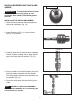
INSTALLING/REMOVING CHUCK AND ARBOR Open Chuck Jaws IMPORTANT! It is important that the chuck and arbor are free of any grease or rust protection. Use ordinary household grease remover. INSTALLING THE CHUCK AND ARBOR 1. Open the chuck jaws as wide as possible to prevent any damage. (Fig. 10) 2. Insert the arbor (A-Fig. 11) into the chuck (B-Fig. 11) as shown. Figure 10 Figure 11 3.
REMOVING THE CHUCK 1. Open the chuck jaws as wide as possible to prevent damage. 2. Lower the spindle until the slot in the spindle is exposed. (Fig. 14) 3. Position the table approximately 1/2” below the extended chuck. Figure 14 4. Turn the chuck until a through hole is exposed in the spindle. 5. Insert the Key-drift provided into the slot. (Fig. 15) 6. Gently tap the key-drift with a mallet to release the chuck. INSTALLING THE TABLE Figure 15 1.
TABLE ADJUSTMENTS Raising and Lowering the Table 1. Loosen the column lock (A-Fig. 19) on the table support bracket (B-Fig. 19). 2. Turn the crank to raise or lower the table to the desired height. A 3. Tighten the column lock (A-Fig. 19). B Figure 19 The table can rotate 360o by loosening the table lock handle and turning to the desired position. (Fig. 20) TILTING THE TABLE 1. Loosen the nut below the table. (Fig. 21) 2. Tilt table to desired angle. 3.
CHANGING SPINDLE SPEEDS CONT. 6. Place the belt on the pulleys in relation to the speed chosen on the speed selection chart starting with the motor pulley first. (Fig. 23) 7. Push the belt tension handle backward on the motor until there is approximately 1/2" deflection in the belt. (Fig. 24) Figure 23 8. Tighten the belt tension lock handle. 9. Close the belt guard. 10. Reconnect the Drill Press to the power. SETTING THE SPINDLE LOCK 1. Loosen the depth stop collar lock (A-Fig. 25) as shown.
Maintenance WARNING: To avoid injury due to unexpected starting, before cleaning or carring out maintenance work, switch off and disconnect the drill press from the power source. 1. Never use water or other liquids to clean the drill press. Use a dry brush. 2. Regular maintenance of the drill press will prevent unnecessary problems. 3. Keep the table clean to ensure accurate cutting. 4. Keep the outside of the machine clean to ensure accurate operation of all moving parts and prevent excessive wear. 5.
Eletrical Requirements In the event of a malfunction or breakdown, grounding provides a path of least resistance for electric current to reduce the risk of electric shock. This tool is equipped with an electric cord having an equipment-grounding conductor and a grounding plug. The plug must be plugged into a matching outlet that is properly installed and grounded in accordance with all local codes and ordinances. Do not modify the plug provided.
Trouble Shooting 15
Parts Explosion 16
Parts List Key No. 1A 2A 3A 4A 6A 7A 8A 9A 10A 11A 12A 13A 14A 15A 16A 17A 18A 19A 3B 4B 5B 6B 7B 8B 9B 10B 11B 12B 1C 2C 3C 4C 5C 6C 7C 8C 9C 10C 11C 12C 13C Part No.
Notes 18
Warranty 2-Year Limited Warranty RIKON Power Tools/Richen Enterprise, Inc. (“Seller”) warrants to only the original retail consumer/purchaser of our products that each product be free from defects in materials and workmanship for a period of two (2) years from the date the product was purchased at retail. This warranty may not be transferred.
For more information: 110 Cummings Park Woburn, MA 01801 877-884-5167/781-933-8400 info@rikontools.com www.rikontools.com Copyright Richen Enterprise, Inc.