Variable Speed Mini Lathe Owner’s Manual Model: 70-200EVS Record the serial number and date of purchase in your manual for future reference. Serial number: Date of purchase: For more information: www.rikontools.com or info@rikontools.com For Parts or Questions: Part # 70-200EVSM1 techsupport@rikontools.
Index 1 GENERAL INFORMATION 1.1 Foreword 2 MACHINE DESCRIPTION 2.1 2.2 2.3 2.4 2.5 2.6 2.7 2.8 Machine identification Getting to know your machine Technical specification Recommended protective clothing Noise emission Prescribed use of the machine Hazards Safety instructions for mini lathe 3 INSTALLATION 4 ADJUSTMENT 4.1 4.2 4.3 4.4 4.
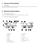
1. General Information 1.1 FOREWORD This manual must be read and understood before operating the machine. This will provide a better working knowledge of the machine, for increased safety and to obtain the best results. 2. Machine Description 2.1 MACHINE IDENTIFICATION There is a plastic identification plate fixed to the machine, containing the specifications, serial number. 2.
2.3 TECHNICAL SPECIFICATION SPECIFICATION 70-200EVS Swing over bed 12" Swing over tool rest base 9-1/2" Working distance between centers 16" Motor 110V/60Hz, 1/2HP Speeds Electronic Variable Speed ranges 400-850, 750-1600, 1500-3000 RPM Spindle thread 1" x 8TPI Headstock taper MT2 Tailstock taper MT2 Hole through spindle 3/8" Ram travel 2-1/2" 2.4 RECOMMENDED PROTECTIVE CLOTHING • • • • Non-slip footwear is recommended.
2.8 SAFETY INSTRUCTIONS FOR MINI LATHES A mini lathe is a tool which due to operator carelessness, cause serious personal injury. It is therefore strongly recommended you read and observe: 1. Do not operate this machine until you have read all of the following instructions. 2. Do not attempt to operate this machine until it is completely assembled. 3. Do not turn ON this machine if any pieces are missing. 4.
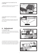
3. Installation CAUTION The machine must not be plugged in and the power switch must FIG. 1 be in the OFF position until assembly is complete. Tool rest 3.1 INSTALLING TOOL REST AND BASE ON LATHE BED Locking arm - Remove the tailstock assembly by releasing the locking handle and sliding the assembly off the end of the lathe bed. Tool rest base - Slide the tool rest base onto the lathe bed and reinstall the tailstock assembly.
3.4 INSTALLING TOOL HOLDER ON THE LATHE BED FIG. 4 - Located the tool holder from the carton, and install it onto the lathe bed with two pan head screws. (See FIG.4) Tool holder FIG. 5 3.5 SECURE LATHE TO A SOLID WORK SURFACE - The lathe must be attached to a solid work surface or stand. FIG. 5 Four mounting holes are easily accessible at the base of the lathe. (See FIG.5) Mounting holes 4. Adjustment FIG. 6 4.
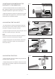
4.2 INSTALLING OR UNINSTALLING THE FACEPLATE TO THE HEADSTOCK FIG. 8 - Thread the faceplate clockwise onto the headstock spindle. Next, engage the spindle lock and stop the spindle from turning, and tighten faceplate with supplied wrench. (See FIG.8) Faceplate Spindle lock - Engage the spindle lock and stop the spindle from turning and loosen faceplate with supplied wrench. Unthread the faceplate anticlockwise from the headstock spindle. FIG. 9 4.
FIG. 12 - To adjust tailstock arm in or out, loosen locking arm and turn handwheel. When the tailstock arm is in a desired position, Tailstock arm tighten locking arm. (See FIG.12) Locking arm Handwheel Locking lever 4.5 CHANGING SPINDLE SPEEDS(FIG.13) - The lathe features three step motor and headstock spindle FIG. 13 pulleys. These three drive ratios are used in conjunction with the electronic variable speed control to provide maximum power and speed when required.
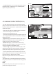
5. Operations FIG. 14 CAUTION Disengage spindle lock before turning the machine on. 5.1. ON/OFF SWITCH (See FIG.14) · To switch ON = press green switch button. · To switch OFF = press red switch button. · To micro-adjust motor speed = Turn micro-adjusting knob. FIG. 15 5.2. TYPICAL OPERATIONS - The lathe is set up for a typical spindle turning operation. (See FIG.15) - The lathe can be set up for a faceplate turning operation.
7. Electrical Requirements In the event of a malfunction or breakdown, grounding provides a path of least resistance for electric current to reduce the risk of electric shock. This tool is equipped with an electric cord having an equipment-grounding conductor and a grounding plug. The plug must be plugged into a matching outlet that is properly installed and grounded in accordance with all local codes and ordinances. Do not modify the plug provided.
27 26 12 29 30 31 26 27 25 1 2 23 28 3 4 24 5 21 22 36 34 35 25 23 6 37 7 38 8 18 19 20 9 39 10 32 29 11 33 17 12 16 40 13 41 14 15 42 56 55 47 46 44 45 43 53 49 50 54 51 58 52 57 59 48 55 56 70 69 68 60 61 62 63 52 64 67 66 65 9.
Parts List Ref No. Description Ref No. Description 1 2 3 4 5 6 7 8 9 10 11 12 13 14 15 16 17 18 19 20 21 22 23 24 25 26 27 28 29 30 31 32 33 34 35 Handwheel Bearing Wave washer Retaining ring Spindle head Spindle lock pin Spring Spindle lock tube Spindle lock nut Cap nut M6 Retaining ring Bearing Spindle Faceplate Spur center Screw M6X16 Spindle pulley Hex.
10.
11. Warranty 5-Year Limited Warranty RIKON Power Tools, Inc. (“Seller”) warrants to only the original retail consumer/purchaser of our products that each product be free from defects in materials and workmanship for a period of five (5) years from the date the product was purchased at retail. This warranty may not be transferred. This warranty does not apply to defects due directly or indirectly to misuse, abuse, negligence, accidents, repairs, alterations, lack of maintenance or normal wear and tear.
For more information: 16 Progress Rd. Billerica, MA 01821 877-884-5167 / 978-528-5380 techsupport@rikontools.com www.rikontools.com Copyright RIKON Power Tools, Inc.