
Use And Care Manual


12
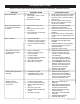
ADJUSTMENTS
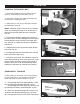
SANDING FRAME ADJUSTMENTS
The sanding frame can be easily adjusted from a
horizontal position to a vertical position, or any other
position to assist your sanding operation.
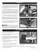
1. Loosen the Hex Screw (#49) that pulls the split
casting together. FIG. 12. This allow the sanding belt
frame to be moved to the work angle desired.
2. Once the sanding belt frame is at the desired work
angle, re-tighten the hex screw to secure it in place.
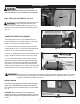
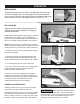
3. In the horizontal position, there are two vertical
padded Hex Screws (#32) that support the sanding
belt frame. These should be checked and adjusted,
if necessary, to make sure that they both touch the
sanding frame Supports (#51). These screws will help
relieve pressure on the casting during work. FIG. 13.
FIG. 12
FIG. 13
Before turning on the machine, review the safety precautions listed on pages 3 to 6. Make
sure that you fully understand the features, adjustments and capabilities of the machine
that are outlined throughout this manual.
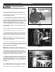
DISC TABLE ADJUSTMENTS CONTINUED
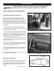
To avoid jamming the work piece or
ngers between the table and
sanding surface, the table edge should be set to a
maximum of 1/16 inches away from sanding surface.
FIG. 11.
FIG. 11
FIG. 14
ON/OFF SWITCH
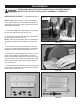
The On/O Locking Switch needs to have the safety
switch key inserted before the switch can be used.
This feature prevents unauthorized use of the sander.
FIG. 14.
CAUTION: Never walk away from sander when
machine is running. Always lock the switch in the O
position and unplug from the power supply when not
in use.
THE MACHINE MUST NOT BE
PLUGGED IN AND THE POWER SWITCH MUST BE IN THE
OFF POSITION UNTIL ALL ADJUSTMENTS ARE COMPLETE.
1/16”
SANDING
FRAME
SUPPORTS
REMOVE SAFETY KEY
TO PREVENT SANDER USE