Operating Instructions C U T T I N G S TAT I O N T Y P E 3 B A S E / T Y P E 5 TA B L E English W I T H A G E N E R AT O R S L 3 5
Copyright by Rinco Ultrasonics AG, Switzerland Version 2.0, gb, Art.-No.
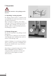
Note Before the machine is unpacked and started up, these operating instructions must be read and their content must be observed when operating the machine. The machine may only be operated, serviced and repaired by persons who are familiar with these operating instructions and the current statutory regulations for health and safety at work.
Contents 1 Explanation of symbols and signs 7 2 Safety information 2.1 General 2.2 Intended purpose 2.3 Special points to note 2.4 Choosing staff 2.5 Installing the units 2.6 Operation 2.7 Noise emissions 2.8 Guarantee 8 8 8 8 8 8 8 9 9 3 Transportation 3.1 Unpacking/receiving inspection 3.2 Damage during transit 3.3 Positioning the plant 10 10 10 11 4 Product Information 4.1 Side view of cutting station 4.1.1 Cutting station 4.1.2 Ultrasonic generator 4.2 Examples for application 4.
10 Cleaning and servicing 10.1 General servicing tasks 10.2 Vibration system and carriage 10.3 Pneumatic group 10.4 Generator 10.5 Oscillating system 10.6 Threaded coupling 52 52 52 53 53 54 54 11 Error messages and trouble shooting 11.1 Error messages/corrective actions: switching on 11.2 Error messages and error elimination during adjustments and welding 11.3 Generator error messages during operation 55 55 12 Electric wiring diagrams 12.1 Wiring diagram for the SL generator 12.1.
Important Please quote the exact type designation and the unit serial numbers in all enquiries concering your Multipress and your Generator. You will find this data on the rating plate (A) at the back of each unit, as well as on the inside cover flap of this operating manual. The design and circuitry of these units are subject to continuous further development and improvement, and represent the latest state of the art.
1 Explanation of symbols and signs Special attention should be paid to passages with the following symbols: Special information or operating instructions. Warnings regarding risk of personal injury or damage to parts of the equipment.
2 Safety information 2.5 Installing the units 2.1 General The design of this unit conforms to the current state of engineering and is safe to operate. The individual modules and the complete unit are subject to continual inspection by our quality assurance department. Always unplug the power cable before making any connections to peripheral units. Be sure to fit the power supply with a grounding connector! Observe any statutory safety regulations in force in ! 2.
2.7 Noise emissions Caution! Limits: Ultrasonic does not cause any damage according to present scientific research as long as the maximum noise level remains below 140 dB and the average level, assuming an 8h/day, remains below 110 dB. Keep an eye on the sub harmonic i.e. audible frequencies, which fluctuate depending on application and are annoying and harmful. Significant are the energy equivalent, continuous sound levels assuming a representative working period (min. 8 h/day max.
3 Transportation Transportation instructions on the packaging must be observed. 3.1 Unpacking / receiving inspection The shipping container used for our machines and units withstands the normal wear and tear of road, rail and air transportation. After receiving the consignment, check whether all the parts conform to the packing list and look for any visible signs of damage. If you discover any damage, notify the carrier immediately and keep the packaging as evidence. B 3.
3.3 Positioning the plant The location of the unit is important. In order to guarantee a long service life, the unit should be installed in clean surroundings. Make sure that the electronic equipment is mounted in a vibration-free environment. The factory settings are performed at 20° C. The ambient temperature can range between 10° C and 45° C during operation.
4 Product Information 4.1 Side view of cutting station 4.1.1 Cutting station 5 1 2 3 4 5 6 7 8 9 10 Main column Support arm of anvil Fixing plate Support arm for insert Pneumatics group Vibration system Anvil Fixing axis of anvil Fixing clamp of anvil Insert carriage 4 10 1 6 2 7 8 9 3 4.1.2 Ultrasonic generator SL35 26 26.
4.2 Examples for application Electric power Power/fuel Generator Driver Converter Motor Booster Gears Sonotrode Drive Ready for welding Ready 4.3 Using ultrasoncis in the plastics and synthetic fabrics industry It is well known that thermoplastic materials come in many shapes and sizes and are used in very different application areas. It is also known that one can cut and weld synthetic fabrics with ultrasonic.
4.4 Advantages of welding and cutting with ultrasonic Ultrasonic welding is used as part of an assembly process for the manufacture of large series of quality products. Its major advantage is the cost effectiveness. Cutting with ultrasonic has the great advantage that it will result in a clean cut and that the edge of the fabric is fused so that any tearing is prevented. Ultrasonic is an environment-friendly technology without additional input materials.
4.6 Technical data of cutting station Dimensions in mm 4.6.1 Insert • Maximum travel of insert: 40 mm • Adjustable depth stop • Precision guides of linear ball bearings in insert • Double action cylinder • Switch for top position of cylinder (optional) • Piezoelectrical converter • Connection thread / fixing thread for sonotrode M 8 4.6.2 Booster Reduce Booster 1:0.5 1:0.6 Colour Material Booster Colour blue aluminium 1:1 violet aluminium 1:1.5 1:2 Further characteristics in 1:2.
4.7 Technical data of ultrasonic generator 4.7.1 Dimensions SL35 Dimensions in mm Weight 7 kg 4.7.2 Concept • Flexible module system with various insert modules. • Clear and simple parameter input with 2- line LCD display. • Optimal efficiency and minimal energy dissipation by using microprocessor regulated frequency control. • Real time microprocessor regulator to maintain constant amplitude under varying loads. • Maintains constant amplitudes during power fluctuations.
4.7.3 Available generator modules Type max. power GM 35-400 GM 35-600 GM 35-900 400 W 600 W 900 W 4.7.4 Connected loads • 230 V 50-60 Hz / maximum current consumption 6.3 A • consumption 110 V (up to 600 W) 4.7.5 Dimensions • see Fig.
5 Control and display elements 5.1 Pneumatic group 1 1 Pressure controller The pressure controller is used to reduce the welding pressure. In order to select a nominal value, pull out the control knob and turn to the required position. Push the knob back in order to fix it in that position. Maximum connection pressure: 7 bar 2 3 4 2 Pressure indicator The pressure gauge indicates the maximum pressure selected for welding.
5.2 Vibration system 4 1 Converter 2 Booster 1 3 Sonotrode 10 2 4 HF connection 10 Carriage insert 3 5.3 Anvil 7 9 Anvil 8 5.4 Fixing axis of anvil 7 8 Fixing axis of anvil 2 5.5 Fixing clamp of anvil 9 Fixing clamp of anvil 5.
5.7 Controls and indicators 26 Generator module grips If necessary, you can pull out the generator module by holding these grips. The fastening screws (34) for opening the generator module are located above and below the grip bars. The generator module is never to be pulled out or plugged in while mains is connected. (high voltage) 27 LED bar This display indicates the power supplied during the welding operation.
30 Key "US-TEST" Key to activate ultrasonics test. The display shows the current horn frequency. If the key is activated formore than 5 seconds, the error message comes on.
6 Commissioning 6.1 Setting up Select the location for setting up the unit under the following criteria: • Clean environment • Firm and level surface • The cutting table area must free from vibrations • Ambient temperature: During operation: 10° C – 45° C While adjusting settings: 20° C 6.2 Space requirement The location where the machine is set-up must afford sufficient space for servicing as well as adjustment activities. 6.
Compressed air connection: maximum 7 bar 4. Connect the pneumatic hose to the pneumatic connection on the cutting station (10).
6.4 Fitting the vibration system It is imperative to switch off the generator prior to fitting the vibration system. 1. Release the screws (1) with the allen key (6 mm). 2. Insert the converter and the booster (already 1 assembled) through the lower part up to the stop and then tighten the screws (1). 3. Connect the HF plug to the HF terminal (2) of the converter and connect the cooling pipe (3).
4. Put the sonotrode (4) in place and fix it with the spanner (5). Tightening moment: 15 – 25 Nm The ultrasound transmission system is now ready for operation.
6.5 Adjustments 1. Release the pressure from the cylinder and set the pressure controller to “0 bar”; lower the insert manually down to the stop above the anvil. 2. Place the cutting edge of the sonotrode exactly to the cutting edge of the anvil at the end of the radius. 3. Release the nut (2) and tighten the screw (1) up to the stop of the cutting table (3). Then remove the sonotrode by a few decimal units from the anvil. 1 4.
6. Switch the unit on using the “ON/OFF” button (32). After the US-TEST, the message >> READY << is shown on the display (28). 7. Use the “SETUP” key to change to the * PARAMETER * >> ADJUST <<.
8. After pressing the “SETUP” key, check all parameters using the “NEXT” key and enter the nominal values, if these are known from the specification. 9. Use the “SETUP” key to change to normal operation and the unit is now ready for the first cut of fabric. Please refer to “Parameter adjustment”, page 34, for further information on the adjustments. * PARAMETER * >> ADJUST << 6.6 Switching off 1. Use the ON/OFF key (32) to switch off the generator.
7 Operation 7.1 Sequence of welding process 7.1.1 Work cycle Manual starter (standard mode) 1. After pressing the two buttons of the two-handed control (START) simultaneously with an interval of 0.3 seconds, the work sequence (cycle) starts. The solenoid valve is activated and the insert is lowered. 2. Continue to press the two-handed controls until the ultrasound is activated. If the two-handed controls are released too early, the insert retracts to its home position.
Impulse (reduced safety) 1. When the two buttons of the two-handed control (START) are pressed simultaneously in an interval of 0.3 seconds, the work sequence (cycle) starts. This activates the solenoid valve and the insert is lowered. From this point onwards the buttons of the two-handed control must not be kept depressed. The ultrasonic is initiated by the trigger. The ultrasonic will stay in operation until the end of the pre-set welding time.
7.1.2 Optimisation In order to optimise the welding process, • only one parameter must be changed at a time, • the welding result must be checked after each change of a parameter. Never change several parameters at the same time. If one changes several parameters at the same time, it is not possible to establish which of the parameters has had an effect on the welding result. 7.1.3 Parameter setup Setting parameters are available according to initialization of generator.
7.1.4 Description of setting parameters Setting [ADJUSTING :] • Press both start buttons within 0.3 seconds to lower the actuator. Keep the start buttons actuated until safety switch is reached. Press start buttons again to move actuator back to the home position. Part counter [PART :] • The part counter steps up by one after each sound welding. Press CLR key to reset part counter. • Maximum display: 9999999 Welding time [WELDTIME :] • Duration of welding. • Setting range: 0.00 – 9.
Trigger [TRIGGER :] • Upon reaching the TRIGGER, the welding is released. • Setting range: 0.00 – 3.99 s This parameter is operative only if the [TRIGGER: TIMER] function is operative in the * SYSTEM--INIT *. After impulse [AFTER.PULSE] • Duration of after impulse after end switch shut off: • Setting range: 0.00 – 1.99 s • Standard setting: 0.00 s Amplitude [AMPLITUDE :] • The amplitude may be reduced from 100% to 60% by step of 5%. A change of the booster may thus be avoided.
7.2 Parameter set-up procedure RINCO ULTRASONIC SWITZERLAND >> US-TEST << ++++++++++++ >> READY << PART : 1234567 An ultrasonic vibration system must be connected. Do not touch horn! 1. Press the ON/OFF key. * PARAMETER * >> ADJUSTING << 2. The generator starts with a two seconds' self-test while warming up. After the self-test the vibration system is tested again for a 1/2 second. 3. Upon termination of tests the message >> READY << PART: 1234567 appears on the display.
7.3 Automatic connection The operating switch (ON / OFF) can be activated or deactivated. To open the generator module (32) it is necessary to, 1. release the four screws (34), 2. pull the handles (26) outwards towards the guides. The steady is in the rear top position (35). Standard position The steady is in the top position and the ON / OFF switch (32) is activated. Automatic option The steady is in the bottom position and the ON / OFF switch (32) is deactivated.
8 Elements 8.1 Converter The converter is a sensitive instrument. Please handle it with great care! The converter (24) is the core of every ultra sonic welding instrument. It belongs to the group of piezoelectric converters. Piezoelectric converters are composed of several ceramics disks that change their shapes under voltage. With an ultra sonic welding converter, an AC voltage with a nominal frequency of (e.g. 20 kHz) is used.
8.2 Booster Applying the correct amplitude to the horn is one of the most important factors in ultra sonic welding. The geometric shape of the horn must be adapted to the object to be welded. Setting the correct amplitude is often difficult. The booster amplifies the amplitude of the converter at a preset ratio. In our example 1:2. The amplification resp. dampening factor is specified as a ratio. The ratio is color coded and has a numerical designation (A).
8.3 Horn Any kind of change to the metallic body of the horn influences the oscillating characteristics and therefore none should be made without consulting the manufacturer! The horn transmits the ultra sonic energy to the object to be welded in form of intense oscillations created by the converter. Work pieces come in various shapes and the horns must be adapted to the shapes as required. The horn is an acoustic body tuned to the frequency of resonance. That sets limits to the shapes it may take.
8.3.1 Horn materials Horns must be made of special high load material. Only high load aluminum, titan and steel alloy are used. The choice of material depends mostly on the intended application. Other factors also influence the choice of material: 1. Rigidity of the material used for the horn in connection with the targeted oscillation amplitude. 2. Surface properties of the work piece and the related surface treatment properties. 3. The sound transmission properties. 4.
8.4 Cutting table for work piece (anvil) The cutting table for the work piece or anvil has several functions: • to maintain the distance between the cutting edge of the work piece and the cutter, • counter plate for the cutter so that this will carry out a clean cut, • absorbing any vibrations and avoiding excessive wear. In many cases, the quality of the cut depends on the shape of the cutting table and the work piece.
9 Replacement 9.1 Replacing the booster Before releasing the converter clamp (2) it is imperative that the main power switch is turned “OFF”. 1 2 1. Release the bolts and the sonotrode (3) using the spanner. 3 2. Release the screw fixing (1) with the allen key (5mm). 3. Pull out the cooling pipe (4). 4. Remove the plug from the HF terminal (5) of the converter. 5. Move the whole vibration system downwards.
6. Move the vibration system through the lower part of the clamp (2) with the booster upwards. 7. Use the allen key 5 to tighten the screws (1) of the clamp (2). 2 1 8. Release the converter (6) with the special span- ner (A) and detach the booster (7) by releasing the screws. 9. If the thread is slightly seized up, loosen the con- verter (6) with a light tap with your hand; use the spanner (A) as shown in figure 5.
A 10. Again release the clamp (2). 11. Pull the booster (7) out. 12. Attach a new booster to the bracket (2) with the thread facing downwards so that it can be screwed to the converter (6).
13. Lock the clamp (2) by tightening the screws (1). 1 14. Make the screw connection between the con- verter (6) and the booster (7) and use the special spanner (A) to pull tight. 7 2 6 A 15. Again release the clamp (2). 16. Pull the converter (6) together with the booster (7) (which has been screwed to the converter) out and turn it.
17. Again place the complete vibration system with the converter (6) uppermost. 5 4 18. Connect the plug to the HF terminal (5) and connect the cooling pipe (4). 7 1 19. Turn the screws (1) to tighten the clamp (2) of the converter. 20. Again make the screw connection between the sonotrode (3) and the booster (7). 21. Tighten the sonotrode (3) with the spanner (8).
22. Align the sonotrode vertically at the anvil by releasing the clamp (2) with the screws (1) and then tightening the clamp (2) again once it has been positioned. 10 1 2 23. Release the fixing clamp of the anvil (9) with the screws (10). Slide the bar of the anvil along until the cutting edge of the sonotrode is placed exactly at the end of the radius; then retighten the clamp (9). 24. For further information regarding the adjustment of the cutting edge see section 6.5 Adjustments.
9.2 Parameter initialization To prepare the Multipress and the Generator for their various tasks, the individual press functions are initialized according to the mode of operation via the generator control system. Press the PREV key and keep this depressed during firing up in order to activate the standard start-up. Press the CLR key in order to confirm the standard start-up. When pressing the SETUP key the standard start-up will be interrupted.
9.2.1 Description of selectable functions START (MANUAL) • The generator must be started up MANUALLY. TRIGGER (FU/TIME) • The TRIGGER can be confirmed with FU or TIME. • Standard setting: FU WELDING TIME (TIME) • The generator must be started up in TIME. VALVE (YES/NO) • The generator must be started up in the YES position. F-C US (YES/NO) • This function is activated when a unit was started with YES.
SOFTSTART (1-9) • The duration from starting up to reaching the full amplitude can be adjusted in 9 steps. 1 Slow start of vibration for sonotrodes with a large volume 9 Fast start of vibration for small sonotrodes • Standard setting: 7 (See illustration) SDF (YES/NO) • This function is not activated unless YES is selected for start-up. • Standard setting: NO • Starting aid for starting up sonotrodes with large volume.
9.2.2 System initialization process RINCO ULTRASONIC SWITZERLAND V2E0 A oscillating system must be connected. Do not touch the horn. 1. Press ON/OFF button. * SYSTEM--INIT * CODE : 000 2. The generator performs a self-test for two seconds during start up. * SYSTEM--INIT * CODE : 472 3. Keep the SETUP key pressed during start up. The display shows: * SYSTEM--INIT * CODE : 000 4. Using the cursor keys, set code to 472. * SYSTEM--INIT * START : MANUAL Acknowledge by pressing the SETUP key. 5.
* SYSTEM--INIT * SOFTSTART : 5 * SYSTEM--INIT * LANGUAGE:ENGLISH * SYSTEM-INIT * AMPLITUDE: OFF * SYSTEM--INIT * SDF : OFF * SYSTEM-INIT * TRIGGER : AFTER 51
10 Cleaning and Servicing 10.1 General servicing tasks 5 4 10 All cleaning and servicing must be carried out by qualified personnel. 1 6 2 Prior to starting servicing, it is imperative to check that all services, such as power and compressed air, have been switched off. 7 8 9 Important: never clean the keyboard and the front of the generator with corrosive agents. 3 Neither the cutting station nor the generator require special servicing.
10.3 Pneumatics group No servicing required. 10.4 Generator Ensure that the display screen of the generator is always clean.
10.5 Oscillating system Work may only be carried out on the vibration system and converter housing when the mains voltage is switched off! High voltage! Avoid contact with the RF connection of the converter. Never connect any measuring instruments to the RF socket of the converter! The converter is electrically charged even after switching off the generator. 10.6 Threaded coupling Converter (24), booster (25) and horn (9) are screwed together.
11 Error messages and trouble shooting Troubleshooting may only be carried out by specially trained staff. In case of doubt, contact the service centre or the manufacturer directly (see appendix). 11.
11.
12 Electric wiring diagrams 12.1 Wiring diagram for the SL generator 12.1.
12.1.2 Manual starter STO2 (standard) Input emergency stop Input N/O 1 Input N/O 2 12.1.
12.1.
12.1.5 Interface STO3 Input US-stop 1 Input US-stop 2 Output reserve NC Input reset Input amplitude Error - max. 24V / 0.5A - open in case of an error Insert in position - max. 24V / 0.
12.
12.3 Listing of fuses Generator GM35-400 GM35-600 GM35-900 Base of mains terminal Bus print Module of generator F1 F2 F3 F4 F5 4 A/T 4 A/T 6,3 A/T 4 A/T 4 A/T 6,3 A/T 400 mA/T 400 mA/T 400 mA/T 4 A/T 4 A/T 6,3 A/T 100 mA/T 100 mA/T 100 mA/T 12.4 Back part of generator SL 35 1 2 3 4 5 STO1 STO2 STO3 STO4 STO5 12.
13 Technical drawings and dimensions 13.
13.2 Amplitude values of the GM generator module series The different generator outputs generate different amplitudes. The value of the amplitude described in the diagram below refers to the respective configuration of the generator/booster/sonotrode. The effective amplitude of the welding is directly listed. 9 24 25 A K1 K2 Sonotrode Converter Booster Amplitude Connecting surface Connecting surface 13.
13.4 Length of screws of the different components of the vibration system for 35 kHz 2.4 Converter The screw is an integral part of the converter, it cannot be removed. 25 Booster The connecting surfaces are placed exactly parallel between the front and connection face. 9.1 9 Sonotrode 9.1 Sonotrode screw The sonotrode screw is manufactured from highly resistant steel or titanium.
14 Addresses of technical customer service The RINCO ULTRASONICS customer service is available for you in case of faults or welding problems. A In order to be able to give you correct advice, our customer service requires the following data: 1. Model and serial number of your unit 2.
R A CREST GROUP COMPANY RINCO ULTRASONICS AG Industriestrasse 4 CH -8590 Romanshorn 1 Switzerland Phone +41 71 466 41 00 Fax +41 71 466 41 01 info@rincoultrasonics.com www.rincoultrasonics.