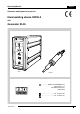
Operating Manual English Ultrasonic welding device for plastics Hand welding device HW35-3 with Generator RL35 RL35 HW35-3 ................. RINCO ULTRASONICS AG Industriestrasse 4 CH-8590 Romanshorn Switzerland ............................... ++41 71 466 41 00 ............................... ++41 71 466 41 01 Version 4.
Note Note Read this operating manual and study it carefully before unpacking and putting the device into operation. The device may only be used, maintained and repaired by persons who are familiar with the operating manual and the applicable regulations concerning working safety and accident prevention.
Table of contents 1 Explanation of symbols and signs ....................................................................... 1-1 2 Safety information ................................................................................................. 2-1 2.1 2.2 2.3 2.4 2.5 2.6 3 Product information .............................................................................................. 3-1 3.1 3.2 3.3 3.4 4 Choice of location ....................................................................
Table of contents 9 Cleaning and maintenance ................................................................................... 9-1 9.1 9.2 9.3 9.4 9.5 General maintenance jobs ....................................................................................................... 9-1 Hand held welding device ......................................................................................................... 9-1 Generator ..............................................................................
Preface Preface Congratulations on having purchased the device. This manual is designed to provide buyers and users with all the information they will need to handle, install, operate and maintain the device. To ensure that the system is always ready for operation, it is necessary to follow the notes and instructions in this manual. The manual is broken down into the following chapters: Chapter Safety information Contains notes and warnings concerning the operation of the welding system.
Important Important! Please quote the exact type designation and the device serial numbers in all enquiries concering your device. You will find this data on the rating plate (A) at the back of the device, as well as on the inside cover flap of this operating manual. The design and circuitry of this device are subject to continuous further development and improvement, and represent the latest state of the art.
Notes # ___________________________________________________________________ ___________________________________________________________________ ___________________________________________________________________ ___________________________________________________________________ ___________________________________________________________________ ___________________________________________________________________ ___________________________________________________________________ ___________________________
Notizen # ___________________________________________________________________ ___________________________________________________________________ ___________________________________________________________________ ___________________________________________________________________ ___________________________________________________________________ ___________________________________________________________________ ___________________________________________________________________ _________________________
Explanation of symbols and signs 1 Explanation of symbols and signs Special attention should be paid to passages with the following symbols: Special information or operating instructions. Warnings regarding risk of personal injury or damage to parts of the equipment. The item numbers used in the illustrations and descriptions, e.g.
Explanation of symbols and signs # ___________________________________________________________________ ___________________________________________________________________ ___________________________________________________________________ ___________________________________________________________________ ___________________________________________________________________ ___________________________________________________________________ ___________________________________________________________________
Safety information 2 Safety information 2.1 General The design of this device conforms to the current state of engineering and is safe to operate. The individual modules and the completedevice are subject to continual inspection by our quality assurance department. 2.2 Intended purpose This device is intended exclusively for the ultrasonic welding of suitable plastics. Any other use is regarded as inconsistent with the intended purpose, and is undertaken at the user's own risk.
Safety information 2.5 Installing the device Always unplug the power cable before making any connections to peripheral devices. Be sure to fit the power supply with a grounding connector! Observe any statutory safety regulations in force in your country! Failure to observe these regulations will exempt the manufacturer from all liability for injury to persons or damage to materials! Before starting up the device, always make sure it is in a closed and safe condition. 2.
Safety information # ___________________________________________________________________ ___________________________________________________________________ ___________________________________________________________________ ___________________________________________________________________ ___________________________________________________________________ ___________________________________________________________________ ___________________________________________________________________ ______________
Safety information # ___________________________________________________________________ ___________________________________________________________________ ___________________________________________________________________ ___________________________________________________________________ ___________________________________________________________________ ___________________________________________________________________ ___________________________________________________________________ ______________
Product information 1 3 Product information 3.1 Product overview 3.1.1 Hand held cutting device 2 1 Housing 2 Trigger switch 3 Horn 4 Suspension 5 Cooling-air connections A Name plate on housing 3.1.2 Ultrasonic generator RL35 26 26.
Product information 3.1.3 Cooling (optional) It is necessary to cool the converter for heavy duty use.
Product information 3.2 Warranty statement With the delivery of this system RINCO ULTRASONICS AG acknowledges its warranty obligation in accordance with VSM (Association of Swiss Machine Builders). Fulfilment of the terms of this warranty by RINCO ULTRASONICS AG shall be conditional, however, on a number of requirements, for example: The user must be familiar with the contents of this Operating Manual. The instructions and warnings contained in this Operating Manual must be observed.
Product information 3.
Product information 3.3.1 Concept - Robust handy housing Ergonomic trigger switch Piezoelectric converter Connecting screw thread for horn: ................................... M8 3.3.2 Compressed air - Dry compressed air, maximum: .................... 7 bar (105 PSI) 3.3.3 Dimensions - Dimensions:................................................ see fig. page 3-4 3.3.4 Weight - Weight ................................................................... ca. 0.7 kg 3.3.
Product information 3.4 Technical data of the Ultrasonic Generator RL35 6 Dimensions in mm Weight: ................................
Product information 3.4.1 Concept - Flexible modular system with various insertable modules. Well arranged and simple input of parameters. Optimum efficiency and low power loss. Detection of system malfunctions. Interface for PLC. 3.4.2 Available generator modules Type UGF 35-250 UGF 35-400 UGF 35-600 UGF 35-900 max. power 250 400 600 900 W W W W 3.4.3 Connected loads - 230 V 50-60 Hz - Optional 200 V 110 V (to 600 W) - Maximum current consumption ....................................... 4 A 3.4.
Product information # ___________________________________________________________________ ___________________________________________________________________ ___________________________________________________________________ ___________________________________________________________________ ___________________________________________________________________ ___________________________________________________________________ ___________________________________________________________________ _____________
Transportation 4 Transportation Transportation instructions on the packaging must be observed. 4.1 Unpacking/receiving inspection The shipping container used for our devices withstands the normal wear and tear of road, rail and air transportation. After receiving the consignment, check whether all the parts conform to the packing list and look for any visible signs of damage. If you discover any damage, notify the carrier immediately and keep the packaging as evidence. 4.
Transportation # ___________________________________________________________________ ___________________________________________________________________ ___________________________________________________________________ ___________________________________________________________________ ___________________________________________________________________ ___________________________________________________________________ ___________________________________________________________________ __________________
Controls and indicators 1 5 Controls and indicators 5.1 Hand held welding device 2 Trigger switch This activates the ultrasonic vibrations. Do not touch horn ! 3 Horn Never alter a tuned horn mechanically. This can result in damage to the vibration system und generator. The horn is the actual sonic tool. It is tuned to the resonance frequency by the manufacturers.
Controls and indicators 5.2 Ultrasonic Generator RL35 26 Generator module handle If necessary, you can pull out the generator module by holding these grips. The fastening screws (33) for opening the generator module are located above and below the grip bars. 2 The generator module is never to be pulled out or plugged in while mains is connected. (high voltage) 27 LED bar This display indicates the power supplied during the welding operation.
Controls and indicators 3 31 Weld time Using this keypad you can - change the weld time. a) increase numeral b) decrease numeral 3a With the initialisation on the internal program selection switch (level 9) following section 8 „Resetting“, the welding time is increased by a factor of ten (99.9 sec.) 32 3a Hold time This setting does not apply to hand held device.
Controls and indicators # ___________________________________________________________________ ___________________________________________________________________ ___________________________________________________________________ ___________________________________________________________________ ___________________________________________________________________ ___________________________________________________________________ ___________________________________________________________________ _________
Initial start-up 6 Initial start-up 6.1 Choice of location Select the location for the device according to the following criteria: - clean surroundings - a base for the electronic devices which is free from vibration - an ambient temperature during operation: . 10 °C - 45 °C when setting: .................. 20 °C 1 6.2 Assembling and connecting up the devices To prepare the devices for operation, carry out the following steps: 1. Connect up the cables between the press and generator.
Initial start-up 2 3 3. Tighten the horn (9) with two spanners of correct size (G/S) Do not touch horn ! 2 3 4. The device is switched on at the main switch (34). The device is ready for operation after a builtin check.
Initial start-up # ___________________________________________________________________ ___________________________________________________________________ ___________________________________________________________________ ___________________________________________________________________ ___________________________________________________________________ ___________________________________________________________________ ___________________________________________________________________ ________________
Initial start-up # ___________________________________________________________________ ___________________________________________________________________ ___________________________________________________________________ ___________________________________________________________________ ___________________________________________________________________ ___________________________________________________________________ ___________________________________________________________________ ________________
Elements 1 7 Elements 7.1 Converter The converter is a sensitive instrument. Please handle with great care! The converter (K) is the core of every ultrasonic welder. It belongs to the category of piezo-electric converters. Piezoelectric converters consist of several ceramic disks that change their size when an electric voltage is applied. In the case of the ultrasonic welding converter, an alternating voltage with the nominal frequency (e.g. 35 kHz) is applied.
Elements 7.3 Horn Any changes to the metallic body of the horn will affect its vibration characteristics and should not be performed without consulting the manufacturer! 3 The horn (3) is the tool that transfers the ultrasonic energy produced by the converter to the welding object in the form of an intensive vibration. Since workpieces come in a variety of forms, horns have to be adapted to the specific requirements. The horn is an acoustic body tuned to the resonance frequency.
Elements to immense mechanical loads. It is extremely important, therefore, to design the horn in such a way as to enable the plastic part to be joined under optimal conditions. The horn surface may have a coating for abrasive plastics for longer service life. RINCO has a long record and a lot of experience in horn manufacture.
Elements # ___________________________________________________________________ ___________________________________________________________________ ___________________________________________________________________ ___________________________________________________________________ ___________________________________________________________________ ___________________________________________________________________ ___________________________________________________________________ ________________________
Retooling 8 Retooling 8.1 Changing horn It is important to ensure that the mains switch on the generator has been switched off before unplugging the HF cable! 1 1. Separate the horn (3) with spanners (G/S). 1 Never put the two parts in a vice or similar tool! 2. Screw on the new welding tool and tighten.
Retooling 8.2 Detailed description of functions from the program selector switch Ultrasonic devices are used in a wide range of fields today, so that users have a variety of different control requirements. A welding installation needs to be able to be connected to the available peripheral devices. For this reason, a number of programmes have been created to suit the most common peripheral requirements.
Retooling The program selection switch has 10 settings. 4 For US-operations without pneumatic tool advance. 4a The standard setting for hand held devices is '0'. 4a Mode Adjustment 0 external welding time 1 internal welding time 9 Pulse with settable welding time; max. 99.9s With setting level ”9”: Toggle switch: Ultra sound operates automatically according to the pre-set time without holding "start 1". Re-activating "start 1": The ultra sound is stopped. If the time has been set at ”00.
Retooling 8.2.2 Afterpulse (shake-off impulse) 5 UGF The afterpulse can be activated with a jumper on the main circuit board. The afterimpulse occurs 0.3 seconds after the holding time has expired. J4 ”Hardware test program” jumper (only for use by the manufacturer) J5 P ”US afterpulse” jumper Main circuit board The standard setting of J4 and J5 is "OFF". 25 ms 75 ms The time of the afterpulse can not be changed. 8.2.
Retooling # ___________________________________________________________________ ___________________________________________________________________ ___________________________________________________________________ ___________________________________________________________________ ___________________________________________________________________ ___________________________________________________________________ ___________________________________________________________________ _______________________
Retooling # ___________________________________________________________________ ___________________________________________________________________ ___________________________________________________________________ ___________________________________________________________________ ___________________________________________________________________ ___________________________________________________________________ ___________________________________________________________________ _______________________
Cleaning and maintenance 9 Cleaning and maintenance 9.1 General maintenance jobs Cleaning and maintenance jobs may only be carried out by specially trained staff. Before beginning maintenance jobs, make sure that all energy sources such as the power and compressed air supply are disconnected. Attention: Never clean the keypad or plastic sheeting of the generator with caustic agents. 1 9.2 Hand held welding device The hand held welding device requires no special maintenance.
Cleaning and maintenance 9.4 Vibration system Work may only be carried out on the vibration system and converter housing when the mains voltage is switched off! High voltage! 2 Avoid contact with the RF socket of the converter. 2 Never connect any measuring instruments to the RF socket of the converter! The converter is electrically charged even after switching off the generator. 9.5 3 Threaded coupling 3 The converter (K) and horn (3) are joined together by threading couplings.
Cleaning and maintenance # ___________________________________________________________________ ___________________________________________________________________ ___________________________________________________________________ ___________________________________________________________________ ___________________________________________________________________ ___________________________________________________________________ ___________________________________________________________________ ________
Cleaning and maintenance # ___________________________________________________________________ ___________________________________________________________________ ___________________________________________________________________ ___________________________________________________________________ ___________________________________________________________________ ___________________________________________________________________ ___________________________________________________________________ ________
Error messages and corrective action 10 Error messages and trouble shooting Troubleshooting may only be carried out by specially trained staff. In case of doubt, contact the service centre or the manufacturer directly (see appendix). 10.
Error messages and corrective action # ___________________________________________________________________ ___________________________________________________________________ ___________________________________________________________________ ___________________________________________________________________ ___________________________________________________________________ ___________________________________________________________________ ________________________________________________________________
Electrical diagrams 11 1 Electrical diagrams 11.1 Wiring diagram for housing 11.1.
Electrical diagrams 11.1.2 Start ST02 manual (optional) 2 input emergency stop input start 1 input start 2 11.1.
Electrical diagrams 11.1.4 Interface ST03 4 US-Stop option A US-Stop option B input US-Stop 1 input US-Stop 2 output piece counter output piece counter Error - max. 24V / 0.
Electrical diagrams 11.1.5 Generator module UGF 5 output converter not used not used not used mains ground mains ground mains P mains P mains N mains N not used GND24V +24V output piece counter (optional): ouput power 0-5V output magnetic valve input start 2 input start 1 input Trigger input US-Stop 2 input US-Stop 1 Error - max. 24V / 0.
Electrical diagrams 11.2 Fuses Generator RL35 6 Fuses are to be found in the following assemblies: Power socket 7 8 9 RL35HWV40/GB/NO7768/16279 Bus print Generator module All fuse dimensions: 5 x 20 mm.
Electrical diagrams 11.3 List of fuses Generator RL35 11.3.1 Fuses 230 volt / 200 volt Generator Power socket F1 F2 Bus print F3 Generator module F4 F5 UGF35-250 3.15 A/T 400 mA/T 3.15 A/T 100 mA/T UGF35-400 4 A/T 400 mA/T 4 A/T 100 mA/T UGF35-600 4 A/T 400 mA/T 4 A/T 100 mA/T UGF35-900 6.3 A/T 400 mA/T 6.3 A/T 100 mA/T 11.3.2 Fuses 110 volt Generator 11-6 Power socket F1 F2 Bus print F3 Generator module F4 F5 UGF35-250-110 6.3 A/T 400 mA/T 6.
Electrical diagrams 11.4 RL 35 Generator rear panel 10 1 STO1 2 STO2 3 STO3 4 STO4 5 STO5 11.5 List of device sockets and connection plugs List of device socket STO1 STO2 STO3 STO4 STO5 Appliance socket Appliance socket Appliance socket Appliance socket Appliance socket RINCO order-No. 14 pol. AMP 7 pol. AMP SUB-D 15 pol. Lemo 1 250V / 8A Liste der Anschluss-Stecker ST1 ST2 ST3 ST4 ST5 Plug Plug Plug Plug Power cable RL35HW/V40/GB/N°7768/16279 5445 5442 5469 7254 5053 RINCO order-No. 14 pol.
Electrical diagrams # ___________________________________________________________________ ___________________________________________________________________ ___________________________________________________________________ ___________________________________________________________________ ___________________________________________________________________ ___________________________________________________________________ ___________________________________________________________________ _____________
Technical drawings and values 12 1 Technical drawings and values 12.1 Amplitude values of the generator RL The different generator outputs result in different amplitudes.The amplitude value described in the following table refers to the respective generator/horn configuration. The effective welding amplitude can thus be read off directly. 3 Horn A Amplitude K Converter K1 Coupling point 12.2 Amplitudes of 35 kHz RL generators 12.2.
Technical drawings and values 4 3 35 kHz 12.
Technical drawings and values # ___________________________________________________________________ ___________________________________________________________________ ___________________________________________________________________ ___________________________________________________________________ ___________________________________________________________________ ___________________________________________________________________ ___________________________________________________________________ ___
Technical drawings and values # ___________________________________________________________________ ___________________________________________________________________ ___________________________________________________________________ ___________________________________________________________________ ___________________________________________________________________ ___________________________________________________________________ ___________________________________________________________________ ___
Service center addresses 13 1 Service center addresses In the event of technical malfunctions or welding problems, the RINCO ULTRASONICS AG Aftersales Technical Service Center will be glad to help. To provide useful advice, our Aftersales Service Center needs the following information: 1. The type designation and serial number of the device. 2. An exact description of the technical malfunction or welding problem. Our address: .................
Service center addresses # ___________________________________________________________________ ___________________________________________________________________ ___________________________________________________________________ ___________________________________________________________________ ___________________________________________________________________ ___________________________________________________________________ ___________________________________________________________________ ________