●
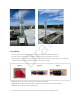
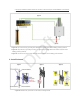
Figure U & X: Crimp and connect the grounding wires on each RF lighting arrestor.
●
●
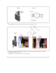
Figure Y: Connect the POE+ cable with the cable gland to the device’s Ethernet port (the base unit should be
automatically powered on from here).
Figure Z: After connecting, tighten the cover of the cable gland.