Tankless Water Heater Installation and Operation Manual INTERNAL (INDOOR) MODELS: Full-length French and Spanish versions available online at rinnai.us CU199i (REU-N3237FFC-US) CU160i (REU-N2530FFC-US) EXTERNAL (OUTDOOR) MODELS: CU199e (REU-N3237WC-US) CU160e (REU-N2530WC-US) Place Model/Serial # Label Here Located in Manual Bag ANSI Z21.10.3 ● CSA 4.
Contents Thank You ..................................................................................................................................................... 3 1. Safety ...................................................................................................................................................... 4 1.1 Safety Symbols............................................................................................................................................. 4 1.
Thank You Thank you for purchasing a Rinnai Tankless Water Heater. Before installing and operating this water heater, be sure to read these instructions completely and carefully to familiarize yourself with the water heater’s features and functionality. If You Need Service To The Consumer Contact your local dealer/distributor or call Rinnai Customer Care at 1-800-621-9419 Monday to Friday between 8 AM to 8 PM ET.
1. Safety WARNING • • • • • If the information in these instructions is not followed exactly, a fire or explosion may result causing property damage, personal injury, or death. Do not store or use gasoline or other flammable vapors and liquids in the vicinity of this or any other appliance. WHAT TO DO IF YOU SMELL GAS: Do not try to light any appliance. Do not touch any electrical switch; do not use any phone in your building. Immediately call your gas supplier from a neighbor’s phone.
1.2 Safety Precautions The following precautions apply to the installer and consumer. Read and follow all instructions in this section. WARNING DO NOT adjust the internal gas valve. The design is such that adjustment is not required. Warranty will be voided if the internal gas valve is adjusted. • Before operating, smell all around the appliance area • • • • • • • • for gas. Be sure to smell next to the floor because some gas is heavier than air and will settle on the floor.
2. About the Water Heater 2.1 Items Included Unpack the Rinnai Tankless Water Heater package and verify the following contents are included. If any items are missing, contact your local dealer/distributor or call Rinnai Customer Care at 1-800-621-9419.
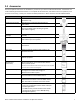
2.4 Accessories Numerous optional accessories are available for purchase for your Rinnai Tankless Water Heater. Listed below are some commonly purchased accessories. For a complete list of accessories, visit www.rinnai.us. For questions, or to purchase an accessory, contact your local Rinnai dealer/distributor or Rinnai Customer Care at 1-800-621-9419. Product Room Air Screen Product Description Recommended air filter/screen for use in room air applications only.
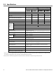
2.5 Specifications Internal (Indoor) Units CU199i External (Outdoor) Units CU160i CU199e 15,000 Minimum Gas Consumption Btu/h Maximum Gas Consumption Btu/h 1 Flow Rate (Min - Max) 199,000 160,000 199,000 160,000 0.26 - 9.8 GPM (1.0 - 37 L/min) 0.26 - 8.0 GPM (1.0 - 30 L/min) 0.26 - 9.8 GPM (1.0 - 37 L/min) 0.26 - 8.0 GPM (1.
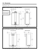
2.6 Dimensions Measurements: in. (mm) Internal (Indoor) Models (CU199i and CU160i) Front Panel View Side Panel View Vent Connection: 2 in. (51 mm) nominal PVC/Polypropylene or 3 in./5 in. Concentric.
Connections (for Internal and External Water Heaters) Measurements: in.
3. Install the Water Heater THIS SECTION IS INTENDED FOR THE INSTALLER Installer qualifications: A trained and qualified professional must install the appliance, inspect it, and leak test the water heater before use. The warranty will be voided due to any improper installation.
3.2 Choose an Installation Location When selecting an installation location, you must ensure that clearances will be met and that the vent length will be within required limits. Consider the installation environment, water quality, and need for freeze protection. Requirements for the gas line, water lines, electrical connection, and condensate disposal can be found in their respective installation sections in this manual.
Internal (Indoor) Water Heaters • Install the water heater as far away as possible from any air inlet vents. Corrosive fumes, sometimes found in hair/ nail salons, spas, or other industries exposed to toxic fumes, may be released through these vents when not in operation. Chemicals that are corrosive in nature should not be stored or used near the water heater or vent termination. This requirement applies to internal (indoor) and external (outdoor) water heaters.
CLEARANCES Top 2 in. (51 mm) 0 in from vent components Bottom/Ground 12 in. (305 mm) Front 0 in. Clearance for servicing is 24 in. (610 mm) in front of water heater Back 0 in. Sides (Left and Right) 2 in. (51 mm) INTERNAL (INDOOR) MODELS EXTERNAL (OUTDOOR) MODELS Top Front Top Side Front Side Add 0.25 in. (6.35 mm) for recess box 0 in. Vent Bottom (Internal/Indoor Models) Front Exhaust Bottom 24 in.
3.3 Mount the Internal (Indoor) Water Heater to the Wall You Will Need: Supplied by Installer: • Rinnai Tankless Water Heater (Internal/Indoor Model) • Wall Mounting Bracket • Level • 4 screws for mounting bracket installation • Screws for top and bottom bracket installation Use appropriate screws for type of wall construction. 1 2 Hold the wall mounting bracket up against the wall and use a level to make sure the bracket is even. Proper operation requires the water heater to be level.
3.4 Mount the External (Outdoor) Water Heater to the Wall You Will Need: • Supplied by Installer: Rinnai Tankless Water Heater (External/Outdoor Model) • Level • Screws for top and bottom bracket installation Use appropriate screws for type of wall construction. Instructions: Securely screw the top and bottom brackets into the wall, making sure the screws are flush with the wall. • Use any of the holes in the top and bottom brackets.
3.5 Vent the Water Heater Guidelines • Internal water heaters can be installed as direct vent or non-direct vent applications. • When installed as Direct Vent, refer to the “Direct Vent Approved Vent Manufacturers and Products” section (within the “1. Direct Vent” section) for a complete list of approved vent manufacturers and products. • When installed as Non-Direct Vent (Room Air), the vent must be Category IV and of a type listed by a national recognized testing agency.
Venting Installation Sequence 1. Install the water heater. 2. Determine the termination method—horizontal or vertical, concentric, or twin pipes, etc. 3. Determine proper location for wall or roof penetration for each termination. 4. Install termination assembly as described in this manual or in the vent manufacturer’s installation instructions. 5. Install air and vent piping from water heater to termination. 6. Slope horizontal exhaust run towards the water heater 1/4 in per foot.
Select a Vent Type Three types of venting options are available: 1 Direct Vent (Concentric Pipe and Twin Pipe) Concentric Pipe Combustion air and exhaust vent directly through a single concentric connection. Hot exhaust exits through the interior tube, while combustion air enters through the outer layer. Twin Pipe Combustion air and exhaust vent directly through separate penetrations.
1 Direct Vent (Concentric Pipe and Twin Pipe) Direct Vent Approved Vent Manufacturers and Products Following is a list of vent components and terminations for Direct Vent installations. Install the correct venting for your model according to the venting manufacturer’s instructions and the guidelines below. The information below is correct at time of publication and is subject to change without notice.
Equivalent Length (ft) Vertical Horizontal Product Description (Concentric Pipe and Twin Pipe) Diagram Direct Vent Manufacturer Part Number Manufacturer 1 ROYAL 2 in./4 in. CONCENTRIC VENT TERMINATIONS (Continued) 52CVKGVS6502 PVC Concentric Vent Kit 2 in. x 16 in. 52CVKGVS6502-28 PVC Concentric Vent Kit 2 in. x 28 in. 52CVKGVS6502-40 PVC Concentric Vent Kit 2 in. x 40 in. 20 20 CENTROTHERM 20 ICRT2439 2 in. x 4 in. Concentric Roof Termination 20 2 in. x 4 in.
Equivalent Length (ft) Vertical Horizontal Product Description Diagram (Concentric Pipe and Twin Pipe) Manufacturer Part Number Direct Vent Manufacturer 1 UBBINK 3 in./5 in. CONCENTRIC VENT TERMINATIONS 223174PP 3/5 Condensing Horizontal Termination Kit 8.7 in. 223176PP 3/5 Condensing Horizontal Termination Kit 12 in. 223177PP 3/5 Condensing Horizontal Termination Kit 21 in. 223186PP 3/5 Condensing Horizontal Diverter Termination Kit 19 in.
Equivalent Length (ft) Vertical Horizontal Diagram (Concentric Pipe and Twin Pipe) Product Description Manufacturer Part Number Direct Vent Manufacturer 1 3CGRLSV Vertical Adapter 3CGRLSH Horizontal Adapter 3CGRVT Vertical Termination 1 6 5 3CGRHT Horizontal Termination 3PPS-VKL/VK-TCL 3 in. x 5 in. Vertical Termination Cap Kit-Concentric DURAVENT METAL-FAB 3 in./5 in. CONCENTRIC VENT TERMINATIONS (Continued) 16 20 3PPS-HKL 3 in. x 5 in.
Equivalent Length (ft) Vertical Diagram Horizontal (Concentric Pipe and Twin Pipe) Manufacturer Part Number Manufacturer Direct Vent Product Description 1 IPEX DURAVENT CENTROTHERM 2 in. TWIN PIPE TERMINATIONS ISELL0287UV 2 in. 87° Long PPS-UV ISTT0220 2 in. Termination Tee ISLPT0202 2 in. Low Profile Wall Termination 2PPS-HTPL 2 in. Twin Pipe Termination 2PPS-HSTL 2 in. Single Horizontal Termination 2PPS-TBL 2 in.
Equivalent Length (ft) Vertical Horizontal Diagram (Concentric Pipe and Twin Pipe) Manufacturer Part Number Manufacturer Direct Vent Product Description 1 DURAVENT CENTROTHERM 3 in. TWIN PIPE TERMINATIONS ISELL0387UV 3 in. 87° Long PPS-UV ISTT0320 3 in. Termination Tee ISLPT0303 3 in. Low Profile Wall Termination 3PPS-HTPL 3 in. Twin Pipe Termination 3PPS-HSTL 3 in. Single Horizontal Termination 3PPS-TBL 3 in.
1 Direct Vent (Concentric Pipe and Twin Pipe) Direct Vent Termination Clearances (For Concentric and Twin Pipe) TERMINATION Clearance in Ref. A also applies to anticipated snow line X AIR SUPPLY INLET V VENT TERMINAL AREA WHERE TERMINAL IS NOT PERMITTTED SNOW Ref A B C Description Clearance above grade, veranda, porch, deck, or balcony Clearance to window or door that may be opened Clearance to permanently closed window Canadian Installations (CSA B149.1) U.S. Installations (ANSI Z223.
1 Direct Vent (Concentric Pipe) Concentric Pipe Overview Combustion air and exhaust vent directly through a single concentric connection. Hot exhaust exits through the interior Exhaust Combustion air Combustion air tube, while combustion air enters through the outer layer. Concentric Pipe Termination Clearances 60 in. (1.52 m) Note: 24 in. (0.61 m) to wall or parapet 12 in. (0.30 m) Between terminals at different levels 12 in. (0.30 m) 60 in. (1.52 m) vertically between terminals 12 in. (0.
1 Direct Vent (Concentric Pipe) Concentric Pipe Installation Instructions 1 Remove and discard screw from concentric flue connection. Mount Concentric Pipe Through Wall If venting through an exterior wall, align the wall mounting bracket template (located in literature bag) to the wall and follow the instructions on the template for appropriate vent hole location. Use a level to make sure the wall mounting bracket is even and level.
1 Direct Vent (Twin Pipe) Twin Pipe Overview Combustion air Combustion air and exhaust vent directly through separate penetrations. Exhaust Twin Pipe Termination Clearances 12 in. (0.30 m) minimum Wall 12 in. (0.30 m) minimum 60 in. (1.5 m) minimum Exhaust Zone Exhaust 12 in. (0.30 m) minimum above combustion air opening Combustion Air 12 in. (0.30 m) above grade or anticipated snow level Roof Exhaust 12 in. (0.30 m) minimum Combustion Air 12 in. (0.
1 Direct Vent (Twin Pipe) Twin Pipe Installation Instructions The water heater is equipped with a 2 in. (51 mm) pipe connection. With the use of a pipe reducer, installers can use a 3 in. (76 mm) pipe for the combustion air and exhaust. WARNING DO NOT apply PVC glues, solvents, or cleaners to the water heater’s combustion air or exhaust gasket connections. Failure to correctly assemble the components according to these instructions may result in property damage, personal injury, or death.
1 Direct Vent (Twin Pipe) Twin Pipe Example Vent Applications Slope horizontal exhaust 1/4 in. per foot towards the water heater. DO NOT slope combustion air pipe towards the water heater. This configuration requires the use of a Concentric Vent Termination 2 in. or 3 in. PVC/CPVC IPEX / Royal Concentric Side Wall Termination Configuration This configuration requires the use of a Concentric Vent Termination 2 in. or 3 in. PVC/CPVC IPEX /Royal Concentric Vertical Termination Configuration 2 in.
2 Non-Direct Vent (Room Air and External) Room Air and External Termination Clearances TERMINATION Clearance in Ref. A also applies to anticipated snow line X AIR SUPPLY INLET V VENT TERMINAL AREA WHERE TERMINAL IS NOT PERMITTTED SNOW Ref Description Canadian Installations (CSA B149.1) Other than direct vent (Outdoor unit and/or Room Air) 12 in. (30 cm) U.S. Installations (ANSI Z223.1 /NFPA 54) Other than direct vent (Outdoor unit and/or Room Air) 12 in. (30 cm) 36 in. (91 cm) 4 ft (1.
2 Non-Direct Vent (Room Air and External) NOTE: Installation of Non-Direct Vent (Room Air) must use listed category IV venting. NOTE: All terminations (horizontal and/or vertical) must terminate 12 in. above grade or anticipated snow level. Termination Clearances for External (Outdoor) Water Heaters 2 in. 12 in. (0.30 m) 36 in. (0.91 m) to ventilated or unventilated soffit or eve vent; or to a deck or porch 60 in. (1.
2 Non-Direct Vent (Room Air) Combustion Air WARNING This water heater requires adequate combustion air for ventilation and dilution of flue gases. Failure to provide adequate combustion air can result in unit failure, fire, explosion, serious bodily injury or death. Use the following methods to ensure adequate combustion air is available for correct and safe operation of this water heater. Important: Combustion air must be free of corrosive chemicals.
2 Non-Direct Vent (Room Air) Combustion Air (Continued) Louvers and Grills When sizing the permanent opening consideration must be taken for the design of the louvers or grills to maintain the required free area required for all gas utilizing equipment in the space. If the free area of the louver or grill design is not available, assume wood louvers will have 25% free area and metal louvers or grills will have 75% free area.
2 Non-Direct Vent (Room Air) Non-Direct Vent (Room Air) Installation Instructions 1 Remove and discard screw from combustion air vent connection. 2 Remove and discard the combustion air vent cap. 3 Install the combustion air vent pipe. Ensure it is properly seated. Secure the combustion air vent pipe to the combustion air vent connection with the supplied screw.
2 Non-Direct Vent (Room Air) Non-Direct Vent (Room Air) Example Vent Applications 2 in. or 3 in. Schedule 40 PVC/CPVC Snorkel Termination Configuration 2 in. or 3 in. Schedule 40 PVC/CPVC Standard Upside Down "U" Vertical Termination Configuration 2 in. or 3 in. Schedule 40 PVC/CPVC Elbow or Tee Side Wall Termination Configuration 2 in. or 3 in. Schedule 40 PVC/CPVC Tee Vertical Termination Configuration Slope horizontal exhaust 1/4 in. per foot towards the water heater.
3 Common Vent (Indoor Units Only. Direct Vent and Non-Direct/Room Air Vent) Common venting allows multiple Rinnai Tankless Water Heaters to share the same vent system. Rinnai water heaters can only be common vented with Schedule 40 PVC/CPVC or with the Rinnai C-Vent Common Vent System.
Common Vent Maximum Equivalent Vent Lengths For the table below: • Header is the main vent pipe into which several vents connect. • Vent Length is the distance from the end of the header to the Header Vent Length vent termination. • Maximum vent length starts at the end of the header system. • Use 10 ft (3 m) as equivalent vent length for 90° elbows. • For use with CU160i and CU199i internal (indoor) tankless water heaters only.
Common Vent Terminations Equivalent Length (ft) Diagram Vertical Product Description Horizontal Various 3 in., 4 in. and 6 in. Schedule 40 PVC/CPVC Terminations Tee 10 90° Elbow 10 45° Elbow 5 40 Ubbink 800-621-9419 www.rinnai.us Product Description Equivalent Length (ft) Web Site Vertical Phone Diagram Part Number Manufacturer Horizontal Rinnai Common Vent Terminations (Ubbink C-Vent) 790096 790095 CVent Roof Termination 6 in. CVent Roof Termination 4in.
Schedule 40 PVC/CPVC Common Vent Guidelines WARNING • • • • PVC solvents (primer and glue) can be extremely flammable. Vapors may cause a flash fire or explosion resulting in property damage, personal injury or death. Keep solvents away from heat, sparks, flames and all other sources of ignition. Do not solder, cut or weld until all vapors have dissipated. PVC solvents are heavier than air causing them to settle at low points of the system. Before Using PVC solvent Disconnect power to the water heater.
Connecting Multiple Water Heaters (Cascade Communication) Secondary 1 NOTE: For proper operation, do not combine different models with cascade communication. Cascade Cable Required: Primary • Cable length: 26 ft (8 m) OR • Cable Length:10 ft (3 m) • One cable required for each water heater. Secondary 2-23 With use of cascade cable(s) up to 24 water heaters can be electronically connected.
Programming Cascade Communication Parameter Settings (Cascade Communication) Refer to the parameter setting section of this manual for instructions on how to access and change parameter settings. SELECTION SETTING # SETTING DESCRIPTION A 08 Cascade Secondary (1-23) Primary 09 Units in Standby (Cascade) 1 2 c 3 4 E F 5 6 08 Cascade: Primary: Select the water heater intended to be the Primary water heater for cascade communication.
3.6 Connect the Water Supply Guidelines • The piping (including soldering materials) and components connected to this appliance must be approved for use in • • • • potable water systems. Purge the water line to remove all debris and air. Debris will damage the water heater. The appliance must not be connected to a system that was previously used with a non-potable water heating appliance. Ensure that the water filter on the water heater is clean and installed.
3.7 Install the Isolation Valves Isolation valves (included with water heater) provide the ability to isolate the water heater from the structure’s plumbing and allow quick and easy access to flush the heat exchanger. The supplied isolation valves meet American National Standard (ANSI Z21.10.3) / Canadian Standard (CSA 4.3) and are ANSI/NSF 61 approved for potable water. To install isolation valves: 1. Apply thread sealant to the exposed threads of the Cold Inlet and Hot Outlet of the water heater. 2.
3.8 Pressure Relief Valve WARNING Water discharged from the pressure relief valve could cause severe burns instantly or death from scalds. Guidelines An approved pressure relief valve is required by the American National Standard (ANSI Z21.10.3) for all water heating systems and shall be accessible for servicing.
Pressure Relief Valve Installation Instructions To install the pressure relief valve, follow the steps below. 1. On the bottom of the tankless water heater, hand tighten the Pressure Relief Valve Assembly and Gasket to the Pressure Relief Valve Union Fitting. 2. Rotate the Pressure Relief Valve Assembly to the desired accessible position. With a wrench, tighten the Union Nut to the Pressure Relief Valve Union Fitting.
3.9 Condensate Condensate Guidelines To prevent condensate damage, follow these guidelines: • • • • • • • Do not plumb the condensate drain with the pressure relief valve; both must be plumbed independently to drain. All condensate must drain and be disposed of according to local codes. Use only corrosion resistant materials for the condensate drain lines such as PVC pipe or plastic hose. The condensate drain pipe (along its entire length) must be at least the same diameter as the drain line (1/2 in.
Condensate Drain Pipe Connection To connect the condensate drain pipe: 1. Apply thread sealant to 1/2 in. MNPT condensate drain port. 2. Thread 1/2 in. NPT fitting onto condensate drain port. 3. Follow the steps in the next section: “Condensate Pump Safety Switch Wiring.” 1/2 in. MNPT Condensate Pump Safety Switch Wiring IMPORTANT: The steps in this section must conform with local codes and the guidelines established by the National Electrical Code (NEC).
3.10 Connect the Gas Supply WARNING • • • • • A licensed professional must install the gas supply. Turn off 120V power supply. Turn off the gas. Gas is flammable. Do not smoke or provide other ignition sources while working with gas. Do not turn on the water heater or gas until all fumes are gone. Instructions To connect the gas supply, follow the instructions below: 1. Install a manual gas control valve in the gas supply line to the water heater.
Gas Pipe Sizing Reference Tables GAS PIPE SIZING CALCULATION WORKSHEET The gas supply must be capable of handling the entire gas load required at the location. Gas line sizing is based on gas type, the pressure drop in the system, the gas pressure supplied, and gas line type. For gas pipe sizing, refer to the National Fuel Gas Code, ANSI Z223.1/NFPA 54, or the Natural Gas and Propane Installation Code, CSA B149.1 Instructions: Enter values in empty boxes.
Natural Gas EXAMPLE Rinnai Model Gas Input: Pressure Drop 3.0 in. w.c. Intended use: Initial supply pressure of 8.0 in. w.c. or greater. Information in table obtained from NFPA 54, ANSI Z223.1 - 2015. Schedule 40 Metallic Pipe Inlet Pressure: Less than 2 psi Specific Gravity: 0.
3.11 Connect the Power Supply WARNING • • Do not use an extension cord or adapter plug with this appliance. • Indoor water heaters are equipped with a three-prong (grounding) plug for your protection against shock hazard and should be plugged directly into a properly grounded three-prong receptacle. Do not cut or remove the grounding terminal from this plug.
3.12 Parameter Settings WARNING DO NOT adjust parameter settings unless specifically instructed to do so. Certain elements of the installation may require adjusting the parameters of the tankless water heater. To adjust the parameters: 1. Locate the PC Board (lower right side of unit). 2. Locate the two push buttons (A and B) on the PC Board. 3. Press the “A” button for 1 second. A B 4. Use the (Up) and (Down) buttons on the controller to select a setting number (see Parameter Settings Table below). 5.
3.13 Service Indicator (Service Soon, 55) This water heater includes a service indicator (Service Soon, SS). When selected in the parameter settings, an SS code will display on the controller indicating that it is time to flush and service the water heater. • Selection is installers preference based on water conditions or other factors that may influence the suggested interval of service. • See the parameter settings section of this manual for selectable service intervals.
3.14 Post-Water Heater Installation Checklist Continued 5 PRESSURE RELIEF VALVE (PRV) YES NO Does the PRV comply with the standard for Relief Valves and Automatic Gas Shutoff Devices for Hot Water Supply Systems ANSI Z21.22, and/or the standard Temperature, Pressure, Temperature and Pressure Relief Valves and Vacuum Relief Valves, CAN1-4.
4. Operate the Water Heater 4.1 Safety Precautions WARNING • • • • If the information in these instructions is not followed exactly, a fire or explosion may result causing property damage, personal injury, or death. Do not store or use gasoline or other flammable vapors and liquids in the vicinity of this or any other appliance. Before operating, smell all around the appliance area for gas. Be sure to smell next to the floor because some gas is heavier than air and will settle on the floor.
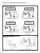
4.2 Controller The controller panel allows you to adjust the water temperature, lock the controller on a set temperature, and view diagnostic information.
4.3 Setting the Temperature This water heater requires a minimum flow rate to operate. This rate can be found on the specification page in this manual. In some cases when you are not getting hot water or if the water alternates between hot and cold, it is due to the water flow being below or close to the minimum flow rate. Increasing the flow rate should resolve these problems in these cases. If you are experiencing issues with higher temperature settings, then reduce the temperature setting.
Available Temperatures with an Internal Controller The water heater can deliver water at only one temperature setting at a time. The available temperatures are provided below. A temperature lower than 98° F (37° C) can be obtained at the tap by mixing with cold water. To change the temperature scale from Celsius to Fahrenheit or vice versa, press and hold the “On/Off” button on the controller for 5 seconds while the water heater is OFF.
4.5 Diagnostic Codes To display diagnostic codes: 1. Turn off the water heater by pressing the “On/Off” button. 2. Press and hold the “On/Off” for 2 seconds and then the button simultaneously. (Up) 3. The last 9 maintenance codes display and flash one after the other. 4. To exit diagnostic codes and return the water heater to normal operation, press and hold the “On/Off” button for 2 seconds and then the (Up) button simultaneously. 2 1 5. Turn on the water heater by pressing the “On/Off” button.
19 21 6 3 Recirculation Low Flow Electrical Grounding • Check all components for electrical short. • Ensure bypass plug is removed and bypass filter is installed. Data Transfer Error • Ensure both the inlet water filter and bypass filter are clean • If the PCB has been replaced, ensure the data transfer • Ensure Parameter setting are correctly set for recirculation (COV Mode) and free of debris. process has been completed. mode. • Ensure Pump supply voltage.
5. Maintain the Water Heater This water heater must be inspected annually by a licensed professional. Repairs and maintenance shall be performed by a licensed professional. The licensed professional must verify proper operation after servicing. WARNING To protect yourself from harm, before performing maintenance: • Turn off the electrical power supply by unplugging the power cord or by turning off the electricity at the circuit breaker. (The temperature controller does not control the electrical power.
FILTERS FREEZE PROTECTION • Water Filter — Clean the inlet water filter by closing the cold and hot water inlet isolation (shut-off) valves. Put a bucket under the filter at the bottom of the water heater to catch any water that is contained inside the unit. Unscrew the water filter. Rinse the filter to remove any debris. Install the filter and open the isolation valves. • Air Filter — See section “5.2 Cleaning and Inspecting the Air Filter” for more information.
5.2 Cleaning and Inspecting the Air Filter (Indoor Units Only) INSPECTION 3. Clean the Air Filter • To maintain optimum performance, periodically inspect the air filter. • If the air filter appears to have lint and/or dust build up, follow the cleaning procedure described below. • If the air filter appears damaged, contact a trained and qualified professional for a replacement air filter assembly. • With mild dish soap and a soft bristle brush, scrub the filter area of the air filter door.
5.3 Flushing the Heat Exchanger This water heater includes a service indicated/reminder (Service Soon, SS). When selected in the parameter settings, an SS code will display on the controller indicating that it is time to flush and service the water heater. Failure to flush the appliance will cause damage to the heat exchanger. Damage caused by lime build-up is not covered by the water heater’s warranty. Rinnai strongly recommends installation of isolation valves to allow for flushing of the heat exchanger.
5.4 Draining the Water Heater WARNING To avoid burns, wait until the equipment cools down before draining the water. The water in the appliance will remain hot after it is turned off. If the water heater is not going to be used during a period of possible freezing weather, it is recommended that the water inside the water heater be drained.
6. Appendices PC BOARD 6.
6.
6.3 Pressure Drop and Water Flow Curves CU199 Pressure Loss (ft of Head) Pressure Loss (PSI) CU160 Dashed lines represent flow rate after parameter adjustment. Water Flow (GPM) The chart below applies only to incoming water temperatures of 70° F (21° C) or less. For incoming water temperatures greater than 70° F (21° C), please contact Rinnai. NOTE: Maximum flow rates may vary based on set temperature, Delta T and altitude.
6.4 Guidelines for Additional Temperature Controllers All Rinnai Tankless Water Heaters are equipped with an integrated digital temperature controller that allows for a precise water temperature set-point. Additional digital temperature controllers are available as accessories and must be purchased separately (detailed installation steps included with purchase). Cable Lengths and Sizes The temperature controller cable should be a non-polarized two-core cable with a minimum gauge of 22 AWG.
6.5 Massachusetts State Gas Regulations FOR GAS MODELS SOLD IN MASSACHUSETTS NOTICE BEFORE INSTALLATION: This direct-vent appliance must be installed by a properly trained licensed professional. If you are not properly trained, you must not install this unit. IMPORTANT: In the State of Massachusetts (248 CMR 4.00 & 5.
6.6 Warranty Limited Warranty for SE+ Series Models • • Internal (Indoor) Models: CU199i and CU160i External (Outdoor) Models: CU199e and CU160e What Is Covered? The Rinnai Standard Limited Warranty covers any defects in materials or workmanship when the product is installed and operated according to Rinnai written installation instructions, subject to the terms within this Limited Warranty document.
What Is Not Covered? This Limited Warranty does not cover any failures or operating difficulties due to the following: • • • • Accident, abuse, or misuse Alteration of the product or any component part Misapplication of this product Improper installation (such as but not limited to) Product being installed in a corrosive environment Condensate damage Improper venting Incorrect gas type Incorrect gas or water pressure Absence of a drain pan under the appliance • Improper maintenance (such as but
7.
100000504 Rinnai Tankless Water Heater Installation and Operation10/2017 Manual